GB - 20
NOTE: A wood block (about 1" square by 5" long) may
be used under pan for blade measurement. Wrap block
with masking tape, mark tape with cutting edge of
blade and measure distance from end of block to
mark(s). This method avoids errors by having to read
any measurements under pan.
NOTE: These adjustments should be made on a level
surface with the tires inflated to the correct air pres-
sure.
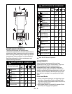
Cutting height range is 1.5" to 4.25" (3.8 –10.8 cm).
Place Tractor on a smooth, flat, level surface. Do the
following:
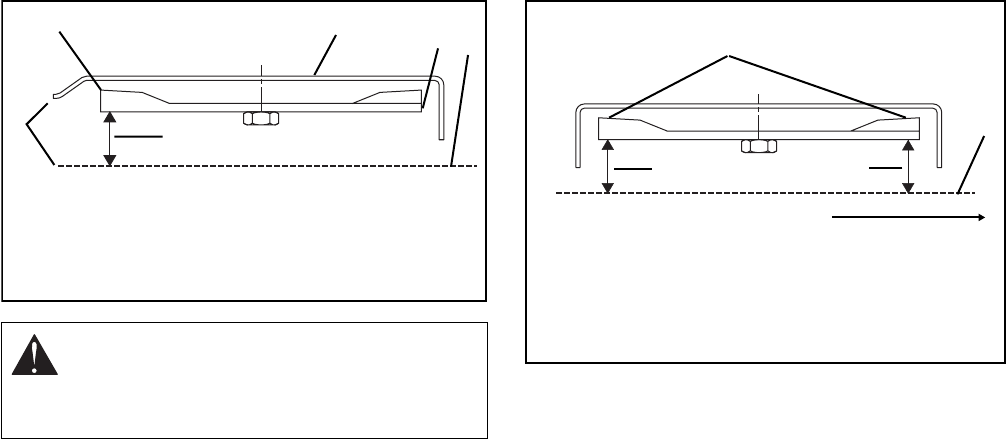
1. With blade(s) positioned side to side, measure
distance of blade(s) tips to floor at right and left
side of mower pan.
2. Rotate blade(s) 180° and check again. The
measurement should be equal within 1/8" side to
side.
To correct for difference in height of blade tips from side
to side,
1. Loosen nuts on adjustment levers (Figure 14).
2. Turn adjustment cap screw clockwise on low side
of mower pan to raise low side one half the
difference in height.
3. Turn adjustment cap screw counterclockwise on
high side to lower high side the other one half of
the height difference.
4. Tighten nuts on adjustment levers.
Mower Pitch and Height
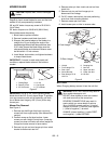
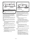
Proper blade pitch is when the blade tip, measured
from the bottom surface (Figure 16), is 1/4" to 3/8"
(6–9 mm) lower at front of mower pan than when same
tip is at rear of mower pan.
Adjusting front lift link raises or lowers front of mower
pan and changes both cutting height and pitch
(Figure 9).
To adjust:
1. Loosen jam nut on front link to allow for
movement of coupling nut.
2. Turn coupling nut clockwise to raise and
counterclockwise to lower front of mower pan.
3. Secure coupling in position by tightening jam nut.
Adjusting rear lift links raises or lowers rear of mower
pan and changes both cutting height and pitch
(Figure 9).
To adjust:
1. Loosen both lower jam nuts to allow for
movement of upper jam nuts on lift rods.
2. Turn both upper jam nuts on each lift rod equally
to raise or lower rear of pan.
3. Secure lift rods in position by tightening lower jam
nuts.
If proper pitch cannot be obtained with front and rear lift
links:
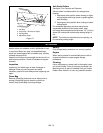
1. Loosen nut on carriage bolt and remove cap
screw holding lift strap and adjustment strap
together (Figure 17).
2. Slide lift strap and adjustment strap together to
raise, or apart to lower rear of pan.
3. Select tapped hole in lift strap that provides
proper adjustment, install cap screw in tapped
hole and tighten nut on carriage bolt to secure.
CAUTION: Rotate mower blade with Mower
Clutch disengaged (OUT) and take
measurements with Mower Clutch engaged
(ON).
1
2
OT0860
1. Cutting Tip
2. Mower Pan
3. Blade
4. Ground Level
5. Cutting Height
6. Discharge Chute
6
3
4
5
Figure 15
Figure 16
2
OT0130
1. Blade Cutting Edges
2. Ground Level
3. Front Blade Height
4. Rear Blade Height
Front of Unit
1
3
4


