GB - 19
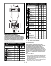
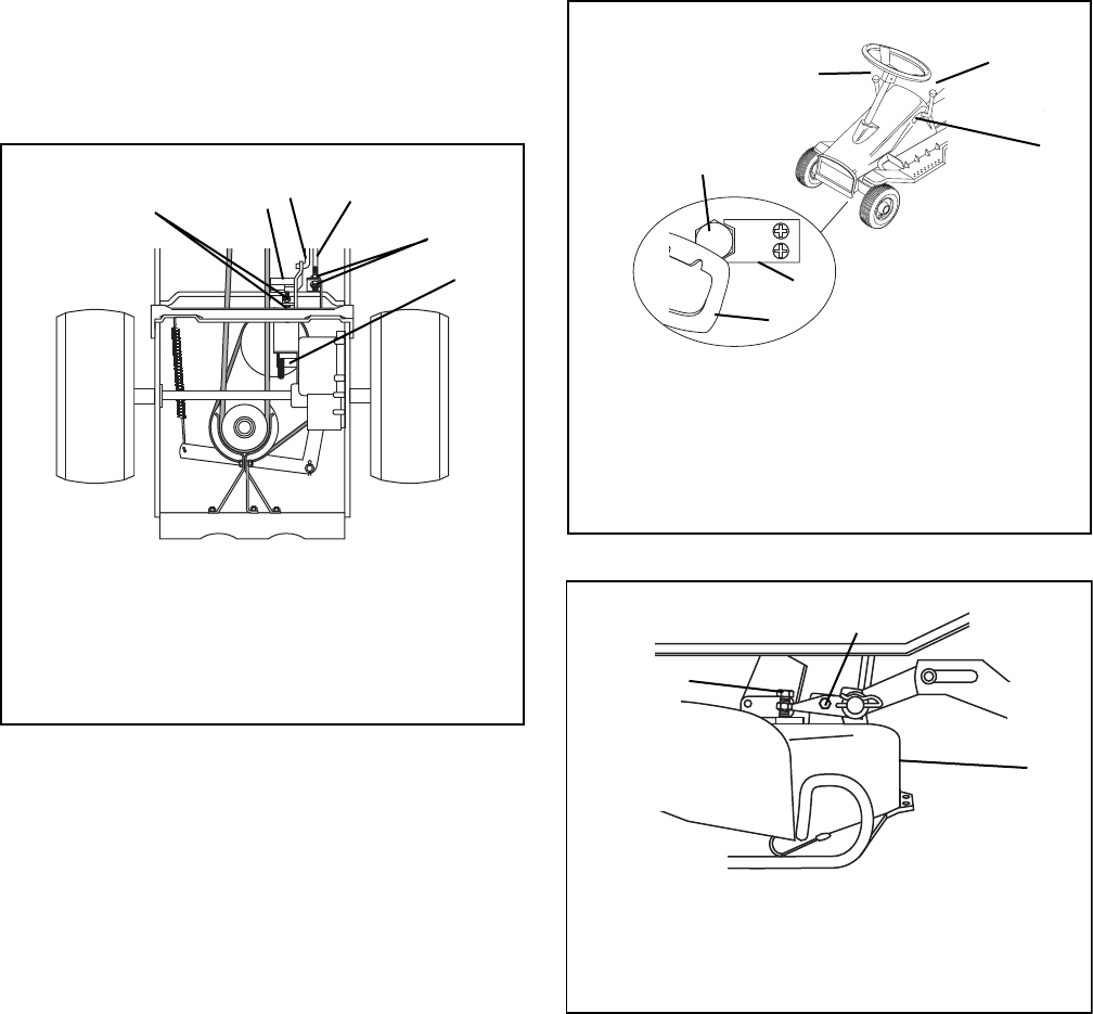
• Adjust double nuts on clutch rod until carrier yoke
clears neutral stop by 1/8 to 1/4 inch (3–6 mm).
• Release Parking Brake and turn both rear wheels by
hand. They should rotate freely in neutral (N) but not
rotate with Speed Selector in any other position.
• Using two 1/2" wrenches (to avoid twisting or
distorting brake band), hold inner adjusting nut with
one wrench and loosen outer lock nut with the other.
• Turn rear wheel by hand while tightening inner
adjustment nut until brake band just binds on hub.
Back off adjusting nut by 1-1/2 turns and secure with
locknut.
• Test by fully depressing Clutch Pedal and trying to
turn wheels by hand. They should not turn.
Mower Belt
Adjust mower belt after first five (5) hours of operation.
To adjust 28" and 30" mowers:
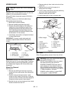
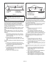
1. Place height control lever in midnotch position,
depress spring clip and tighten yoke on front of
unit with a 3/4" socket wrench (Figure 13).
2. When tightening cap screw, hold Mower Clutch
lever so that front edge of lever is positioned in
line with rear edge of forward notch of quadrant.
3. Tighten belt just enough to prevent slippage
under load. Mower Clutch lever (when tightening
cap screw) will move slightly to rear of this point
when tension is correct.
To adjust the 32" mower:
1. The 32" mower belt clutch rod should be adjusted
so the compressed spring length is from 5-1/4" to
5-3/8" (13.3–13.7 cm) when belt is engaged
(See Figure 7 on page 14).
2. Belt engagement should occur when front edge
of Mower Clutch is positioned in line with rear
edge of forward notch of quadrant (as viewed
through slot in left side of cowl).
3. Full locked-in engagement should occur when
lever is positioned completely into front notch of
quadrant. (Some resistance should be felt when
moving lever into notch.)
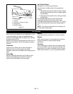
Mower Level (Side to Side)
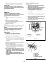
1. Neutral Stop
2. Brake Rod
3. Clutch Rod
4. Clutch Adjustment
Nuts
5. Brake adjustment
Nuts
6. Brake Band
Figure 12
1
2
3
6
4
5
1. Steering Gear
2. Adjustment Cap Screw
3. Height Control
4. Height Lever
5. View Quadrant Through
Slot
6. Spring Clip
Figure 13
1
2
3
4
5
6
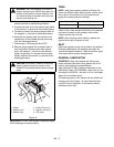
1. Adjustment Cap Screw
2. Adjustment Lever
3. Mower Pan
Figure 14
1
2
3


