


GB - 27
5. Adjust spring extension.
a.With the traction drive clutch lever disengaged,
loosen the jam nut on the cable adjuster.
b.Turn the adjuster body up the cable for more
spring extension.
c.Turn the adjuster body down the cable for less
spring extension.
d.Finger tighten the jam nut, and then hold the
adjuster body with pliers and tighten the jam nut
with wrench.
6. Measure the extension of the traction drive clutch
spring.
7. Repeat step 5 until traction drive clutch spring
lengthens 1/2 -11/16 in.(12.7-17.5 mm) when the
traction drive clutch lever is engaged.
8. With the clutch disengaged, check that there is
more than 1/32 in. (0.8 mm) clearance between
friction disc and drive plate assembly.
IMPORTANT: If spring length cannot be adjusted
within specified range, see your Dealer for repairs.
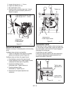
ATTACHMENT DRIVE BELT REPLACEMENT
Remove old attachment drive belt:
1. Shut off engine and allow to cool completely.
2. Remove belt cover (Figure 33).
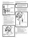
3. Remove hair pin under the control panel
connecting the discharge chute rod from the
chute rotation lever and slide the discharge chute
rod forward.
IMPORTANT: Disconnect chute lock cable and
deflector cable, if equipped.
4. Remove belt finger (Figure 34).
IMPORTANT: Use care when rotating the belt fingers.
DO NOT bend belt fingers out of shape.
5. Remove attachment drive belt from engine
sheave (it may be necessary to turn engine
sheave using recoil starter handle).
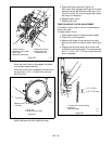
IMPORTANT: To avoid bending bottom cover when
tipping unit apart, support handlebars firmly or tip unit
up on housing and remove bottom cover by removing
six cap screws before separating unit.
6. Support Sno-Thro frame and housing.
7. Remove hex bolts securing housing to frame
(three on each side). Tip housing and frame apart
on pivot pins (Figure 33).
8. Remove attachment drive belt from attachment
pulley (hold brake away from belt).
CAUTION: Always support Sno-Thro frame
and blower housing when loosening the cap
screws holding them together. Never loosen
cap screws while unit is in service position.
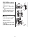
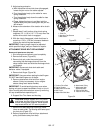
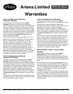
Figure 33
1.Pivot Pin
2.Housing Cap Screws
3.Belt Cover
2
3
1
OS7215
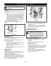
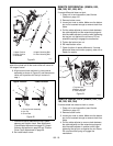
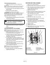
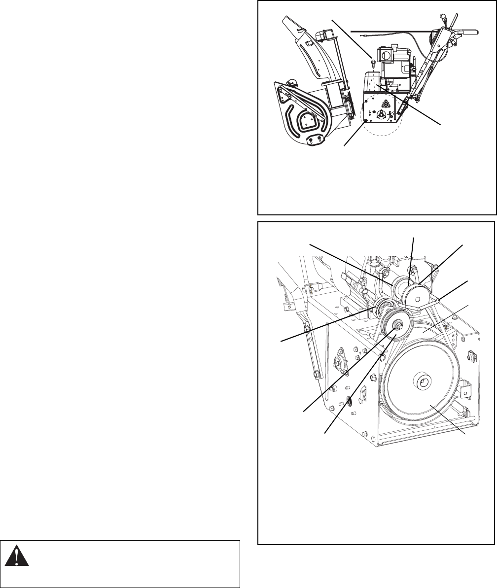
Figure 34
1.Traction Drive Belt
2.Engine Sheave
3.Attachment Drive Belt
4.Belt Finger
5.Attachment Belt Idler
6.Attachment Pulley
7.Attachment Idler
Adjustment Nut
8.Traction Belt Idler
9.Traction Drive Pulley
OS7220
1
2
3
4
5
8
9
6
7