


GB - 10
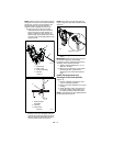
NOTE: After the chute rod has been inserted
through the hex hole in the control assembly,
placing the unit in the service position (see
Service Position on page 22) will ease
alignment and installation of the hair pin.
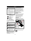
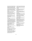
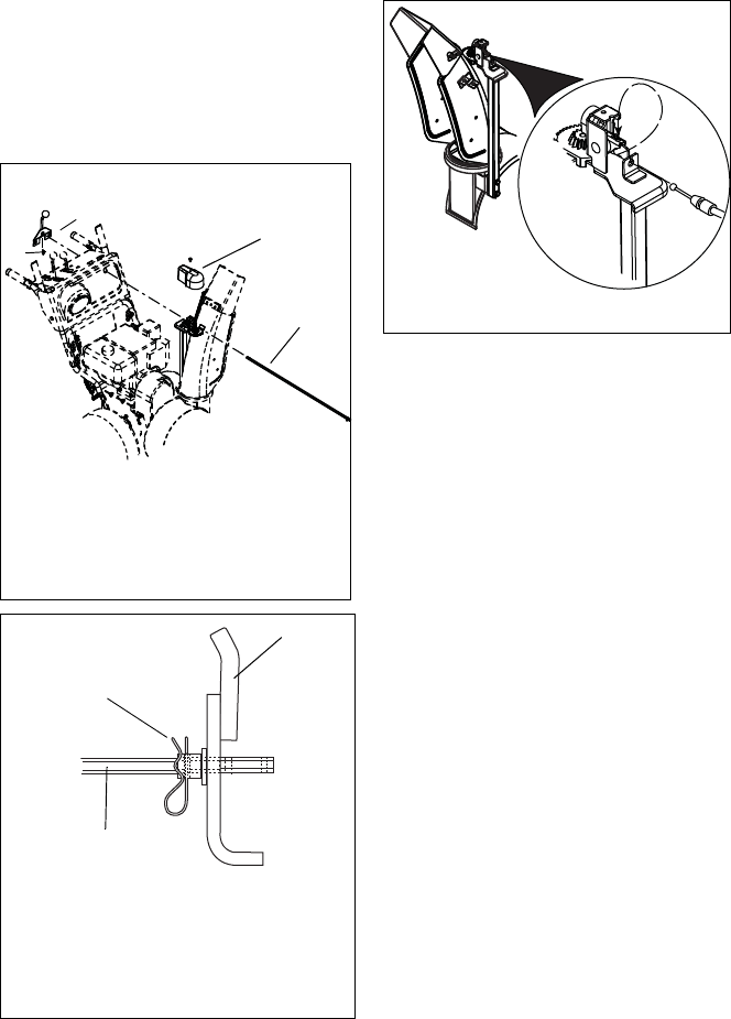
8. Secure the chute rod to the control
assembly with the hair pin removed in
step 6 using the end hole location as
shown in Figure 8. Insert the hair pin
with the loop end to the left of the chute
rod so the control assembly follows a full
range of travel.
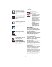
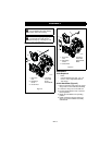
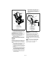
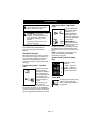
9. Insert the chute lock cable fitting into the
bracket on the chute pedestal, and then
connect the chute lock cable to the lock
teeth by fitting the cable ball end into the
slot on the lock teeth. See Figure 9.
NOTE: Press down on lock teeth with your
finger to align the cable ball end with the slot
(Figure 9).
10. Replace the gear cover removed in
step 4.
IMPORTANT: Rotate the discharge chute to
the left when tightening the pedestal
hardware to ensure clearance between the
discharge chute and the belt cover.
11. Tighten pedestal hardware to 15 – 31
lbf-ft (20 – 42 N•m).
12. Make sure the discharge chute rotates
left and right when you push the
discharge chute control lever left and
right.
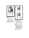
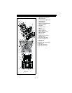
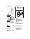
Install Discharge Chute and
Discharge Chute Crank (921005)
(Figure 10)
1. Grease underside of discharge chute
ring (if not already greased).
2. Remove mounting hardware from auger
housing.
3. Install discharge chute over opening in
the auger housing. Finger tighten the
mounting hardware removed in step 2.
NOTE: Leave discharge chute pedestal loose
to help install the chute rod.
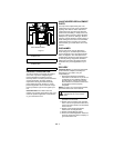
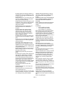
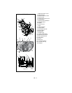
Figure 7
1. Chute Rod
2. Gear Cover
3. Control Assembly
4. Hair Pin
1
2
3
4
OS7432
921004, 006, 007, 008, 009
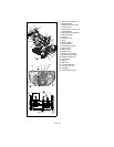
Figure 8
1. Chute Control
Assembly
2. Hair Pin
3. Chute Rod
1
2
3
OS7157
Figure 9
OS7271