


GB - 27
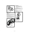
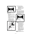
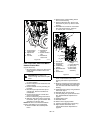
FRICTION DISC REPLACEMENT
Remove Friction Disc
(Figure 30 and 31):
1. Shut off engine, remove key, disconnect
spark plug wire and allow unit to cool
completely.
2. Place the unit into the service position
on a level surface.
3. Remove lockpins from wheel axles and
remove wheels.
4. Remove bottom cover by removing six
hex bolts.
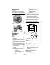
5. Disconnect pivot pin from the speed
selector arm. Save the hardware for
reinstallation.
6. Remove spring clip pin nearest drive
gear from hex shaft.
7. Remove left bearing flange from frame.
8. Slide hex shaft to the left to remove the
flat washer, pinion gear and friction disc
assembly from the hex shaft.
NOTE: Be sure to save washers between
bearing and sliding fork for reassembly.
9. Remove friction disc assembly from
frame.
10. Remove three screws holding friction
disc to carrier bearing.
11. Remove old friction disc. Put the new
friction disc in place, cup side to carrier
bearing.
12. Reinstall three screws into new friction
disc and carrier bearing. Torque to
5 – 6 lbf-ft. (6.8 – 8.13 N•m).
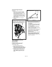
13. Insert new friction disc assembly into
frame. Install washers onto carrier
bearing and slide into speed selector
arm.
14. Slide hex shaft through new friction disc
assembly. Install pinion gear and washer
onto hex shaft and slide shaft into right
bearing.
15. Install left bearing flange using hardware
removed in step 7.
16. Reinstall clip pin into hex shaft.
17. Connect pivot pin to speed selector arm.
See Speed Selector Adjustment on
page 21.
18. Install bottom cover.
19. Reinstall wheels.
20. Return unit to upright position.
21. Connect spark plug wire to spark plug.
22. Adjust traction drive clutch. See
Traction Drive Clutch Adjustment on
page 26.
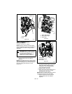
CAUTION: Before tipping unit,
remove enough fuel so that no spills
occur.
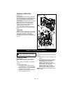
Figure 30
1. Traction Drive
Clutch Cable
2. Adjustment
Barrel
3. Jam Nut
4. Adjustment
Pivot Pin
5. Speed Selector
Arm
6. Attachment
Clutch Arm
OS8175
1
2
3
4
5
6
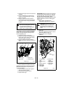
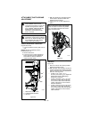
1. Hex Shaft
2. Friction Disc
Assembly
3. Left Bearing
Flange
4. Speed Selector
Arm
5. Friction Disc
6. Right Bearing
Flange
7. Carrier Bearing
8. Spring Clip
9. Drive Gear
10.Drive Plate
Assembly
OS8095
Figure 31
1
2
3
4
6
7
5
8
9
10