


GB - 25
ATTACHMENT DRIVE BELT
REPLACEMENT
Remove Attachment Drive Belt
(Figures 25, 26 and 27)
1. Shut off engine, remove key, disconnect
spark plug wire and allow unit to cool
completely.
2. Loosen the hardware securing belt
cover to unit.
NOTE: DO NOT completely remove the
hardware from unit.
3. Remove belt cover.
4. Remove hairpin from chute crank and
separate.
5. 920015 - Remove remote deflector
control cable from dash control.
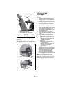
6. Remove belt finger by removing cap
screws mounting belt finger to engine
(Figure 26 or Figure 27).
7. Remove attachment drive belt from
engine sheave (it may be necessary to
turn engine sheave using recoil starter
handle).
IMPORTANT: To avoid bending bottom cover,
when tipping unit apart, support handlebars
firmly or tip unit up on housing and remove
bottom cover by removing six cap screws
before separating unit.
8. Support Sno-Thro frame and housing.
9. Remove hex bolts securing housing to
frame (two on each side). Tip housing
and frame apart on pivot pin.
10. Separate housing from unit.
11. Remove attachment drive belt from
attachment pulley.
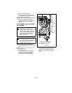
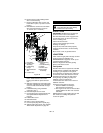
Replace Attachment Drive Belt
1. Place new belt onto attachment pulley
(Figure 26).
NOTE: Engage attachment clutch lever while
connecting housing to frame to hold brake out
of the way.
2. Tip housing and frame back together
and secure with hex bolts.
3. Place belt onto engine sheave.
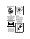
4. Replace belt finger.
IMPORTANT: With the clutch lever engaged,
the belt finger located opposite the belt idler
must be less than 1/8 in. (3,2 mm) from the
belt, but not touching the belt, or belt
grabbing may occur causing impeller to rotate
while the attachment clutch is disengaged
(Figure 27).
5. Adjust clutch per Attachment
Clutch/Brake Adjustment on page 27.
6. Replace chute crank and secure with
hairpin.
920015 - Reconnect remote deflector
cable to dash control.
CAUTION: Always support Sno-Thro
frame and housing when loosening
the cap screws holding them
together. Never loosen cap screws
while unit is in service position.
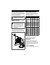
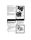
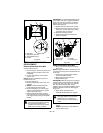
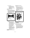
Figure 24
1. Shift Rod
2. Adjustment Pivot Pin
3. Speed Selector Arm
4. Hairpin
2
4
1
3
OS8225
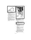
WARNING: AVOID INJURY. Auger
must stop within 5 seconds when
attachment lever is released or
serious injury or unit damage may
result.
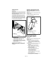
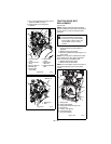
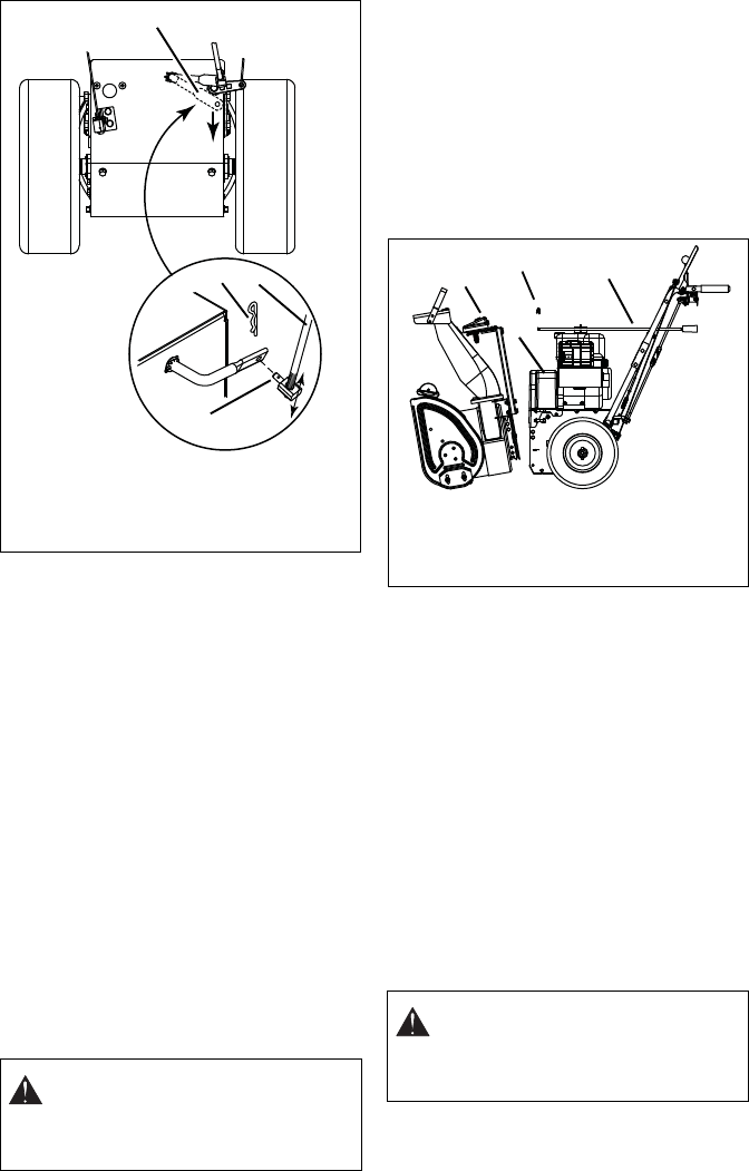
Figure 25
1
2
3
4
1. Pinion Gear
2. Belt Cover
3. Hairpin
4. Chute Crank
OS8230