


GB - 20
2. Check the adjustment and readjust as
needed.
NOTE: If the gap between the friction disc
and aluminum drive plate cannot be adjusted
to this tolerance, take the unit to an
authorized service dealer for repairs.
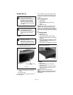
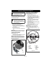
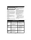
SPEED CONTROL BELL CRANK
(SELF-PROPELLED MODELS)
The speed control bell crank holds the speed
control rod in position after a speed has been
set. The spring washers may become loose
with normal wear. If the speed control rod
does not stay firmly in position, adjust the
speed control bell crank. See Figure 19.
To adjust:
1. Remove cover, fully compress the
helical spring lock washers with lock nut
and then back lock nut off, one quarter
turn.
2. If the speed control rod is still too loose,
tighten lock nut by small increments until
it holds its position. Tightening the lock
nut too much will not allow the speed
control rod to move at all.
3. Align notch in left hand side of cover with
bolt and secure with knob.
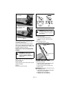
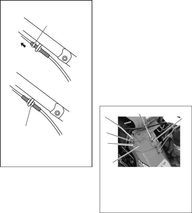
Figure 18
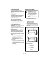
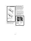
To decrease the gap,
loosen the upper cable
nut.
Then tighten the lower
cable nut against the
bracket.
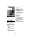
1. Lock Nut
2. Helical Spring
Lock Washers
3. Speed Control
Bell Crank
4. Swivel
5. Hair Pin
6. Speed Control
Rod
Figure 19
OM1670
1
5
2
3
4
6