4 - 15
4.8 ATTACHMENT DRIVE BELT
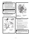
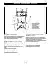
To Replace the Attachment Drive Belt:
1. Shut off engine and allow to cool completely.
2. Place unit in Belt Service Position.
3. Support handlebar.
4. Loosen lower cap screws holding attachment to
frame (one on each side).
5. Remove upper cap screws.
6. Separate housing from unit. Lower handlebars on
floor.
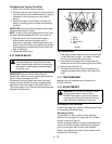
7. Remove attachment drive belt from sheave (hold
brake away from belt).
8. Place new belt onto sheave and while holding
brake out of way, tip unit together.
9. Replace attachment drive belt in reverse order
making sure sheaves align. If alignment is
necessary, loosen attachment sheave set screws,
reposition sheave and retighten set screws.
4.9 TRACTION DRIVE BELT
WARNING:
IMPROPER ADJUSTMENT
could result in death or serious injury.
IMPELLER BRAKE MUST DISENGAGE
when clutch is engaged. Brake must be at
least 1/16" (1.6 mm) to 1/8" (3.2 mm)
minimum from belt when disengaged.
BELT FINGERS MUST BE between 1/16 to
1/8" from belt with attachment clutch engaged
or belt grabbing may occur causing impeller to
rotate while attachment clutch is disengaged.
WARNING:
ROTATING PARTS can cut or
amputate body parts. Keep hands and feet
away. Loose clothing, long hair or scarves can
get caught in rotating parts and cause death
or serious injury.
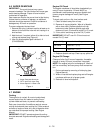
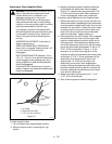
Figure 5
OS0792
1. Housing Bolt Holes
2. Belt Cover
3. Chute Crank
4. Hair Pin
5. Pinion and Gear
6. Chute Strap
7. Cap Screws
2
3
4
1
5
7
6
WARNING:
ROTATING PARTS can cut or
amputate body parts. Keep hands and feet
away. Loose clothing, long hair or scarves can
get caught in rotating parts and cause death
or serious injury.
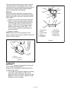
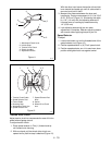
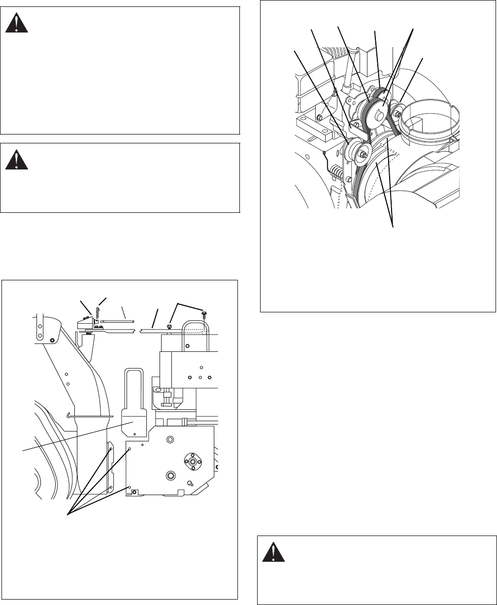
Figure 6
OS0461
1. Attachment Belt Idler
2. Belt Finger
3. Attachment Drive Belt
4. Traction Drive Belt
5. Traction Belt Idler
6. Engine Pulleys
7. Sheaves
1
2
3
4
5
6
7


