


Electrical
A Ground Fault Circuit Interrupter (GFCI)
is required in the circuit. For size of GFCI
required and test procedures for GFCI,
see manufacturer’s instructions.
• Never ground to a gas supply line.
• To avoid dangerous or fatal electrical
shock: turn OFF, disconnect the power
at its source, lock out power to motor,
and place a tag on the dedicated GFCI
circuit breaker indicating the power
is to remain OFF before working on
electrical connections.
Ground Fault Circuit Interrupter (GFCI) trip-
ping indicates an electrical problem. If GFCI
trips, determine the reason for tripping. If
you are uncertain, have a qualifi ed electri-
cian inspect and repair the electrical system.
Verify supply voltage matches the nameplate
voltage. Incorrect voltage can cause fi re or
seriously damage motor and voids warranty.
VOLTAGE
Voltage at motor must be within 10% of
the motor nameplate rated voltage or
motor may overheat, causing overload
tripping and reduced component life.
Verify voltage is correct before applying
power. If voltage does not fall within the
specifi ed range during operation consult
the power company.
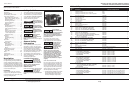
The pumps are shipped with motors
wired for 208-230 volt operation. The
3/4, 1 and 1-1/2 HP models are equipped
with a voltage change device for
115/208-230 operation. Refer to the mo-
tor nameplate for 115 Volt hook-up.
GROUNDING/BONDING
Install, ground, bond and wire motor
according to local or National Electrical
Code requirements. Permanently ground
the motor. Use ground terminal provided
in the terminal box on the back of the
motor. Use size and type wire required
by local codes. Connect motor ground
terminal to electrical service ground.
Bond motor to pool structure. Use a
solid copper conductor, size No. 8 AWG
or larger. Run wire from external bond-
ing lug to reinforcing rod or mesh.
Use solid copper bonding conductor not
smaller than 8 AWG (8.4 mm
2
) from the
accessible wire connector on the mo-
tor to all metal parts of the swimming
pool or spa structure and to all electrical
equipment, metal conduit, and metal
piping within 5 feet (1-1/2 m) of the in-
side walls of the swimming pool or spa.
WIRING
Follow all national and local wiring codes.
If unsure of code requirements consult a
professional electrician. Pump must be per-
manently connected to a dedicated circuit. If
unsure consult a licensed electrician.
NOTE: All electrical wiring and components
must be selected and installed in confor-
mance with the latest NEC requirements
and local codes. If you are unsure about the
requirements consult a licensed electrician
familiar with the requirements.
Operation
Do not run pump dry. Fill pump with
water before starting motor.
Before removing trap cover:
1. CLOSE GATE VALVES in suction and
discharge pipes
2. RELEASE ALL PRESSURE from pump
and piping system
If pump is being pressure tested, be
sure pressure has been released before
removing trap cover.
Do not block pump suction. To do so
with body may cause severe or fatal
injury. Small children using pool must
ALWAYS have close adult supervision.
Fire and burn hazard.
Motor runs at high
temperatures, to reduce the risk of fi re,
do not allow debris, or foreign matter
to collect around the pump motor.
Allow motor to cool prior to handling or
performing maintenance.
The motor is equipped with an internal
thermal protection circuit to guard against
overheating. The maximum ambient
temperature for motor operation must not
exceed rating on motor model plate.
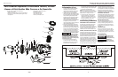
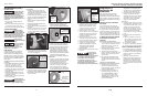
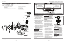
PRIMING PUMP
Release all pressure from fi lter, pump,
and piping system; see the fi lter owner’s
manual. In a fl ooded suction system (water
source higher than pump), pump will prime
automatically when suction and discharge
valves are opened. If pump is located above
the normal pool water level remove ring
and cover assembly and slowly fi ll basket
and pump with water. Clean and inspect
o-ring; reinstall on trap. Replace ring and
cover assembly rotate clockwise to tighten
cover (see Figure 3).
Clamp ring must engage with pump body.
Push down and rotate until internal stops
are felt. Properly aligned tabs shown above
in Figure 3, assure lid is securely clamped.
Failure to tighten clamp ring as indicated
will reduce product strength, resulting in
failure of components, and bodily injury.
Pump prime time will
depend on vertical
distance and length of suction line. If pump
does not prime, make sure that all valves
are open, suction pipe is submerged. Verify
there are no leaks in suction lines. See
Troubleshooting Guide for further assistance.
Maintenance
All AquaPRO
®
Systems pumps are shipped
from the factory with DANGER and/or
WARNING labels already on the pump. These
labels contain a series of basic, yet extremely
important safety messages for the user and
bystander. Regardless of how well these la-
bels are attached or how scratch resistant or
wear-resistant they may be, it is possible that,
in time, the wording may become illegible
with normal use. Whenever you are repair-
ing the pump, performing routine mainte-
nance, or have the opportunity to inspect
the pump, make sure the label is readable.
If the label is not legible, replace the label
with an adhesive version that is available at
no charge by calling AquaPRO
®
Systems at
1-877-278-2797.
Use only parts supplied by manufacturer.
Similar looking parts may not have suf-
fi cient strength for safe operation.
The only routine maintenance needed
is inspection/cleaning of strainer basket.
Debris or trash that collects in basket will
choke off water fl ow through the pump.
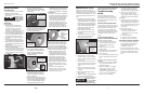
Before attempting to clean basket:
A. Stop pump, disconnect power at its
source, lock out power, place tag on
the dedicated GFCI circuit breaker
indicating the power is to remain
OFF, close valves in suction and
discharge, and release pressure from
system.
Hazardous suction
can trap hair or body
parts, causing severe injury or death. Do
not block suction.
B. Remove ring and cover assembly by
turning counterclockwise. If necessary,
tap handles gently with a rubber mallet.
C. Remove basket and clean. Inspect
holes in basket for blockage. Clean
basket with water and replace in
basket housing. Verify basket is
oriented correctly in housing.
D. Clean and inspect lid o-ring; reinstall
ring and cover assembly.
E. Prime pump (see priming instructions).
5
www.aquaprosystems.com
APB075PRO, APB100PRO, APB150PRO, APB200PRO, APB300PRO,
APB100UPRO, APB150UPRO, APB200UPRO and APB250UPRO
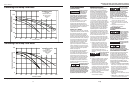
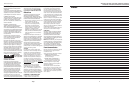
20 Sp
Manual del usuario
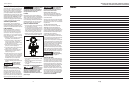
0
20
40
60
80
100
0 20 40 60 80 100 120 140 160
Caudal en USGPM
Carga hidrostática dinámica total en pies de agua
AquaPRO Systems
Sobre carga
Curvas características
60 ciclos 1 fase
3450 RPM
10/
APB100UPRO
1 HP
APB150UPRO
1.5 HP
APB200UPRO
2 HP
APB250UPRO
2.5 HP
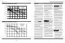
Caudales de la bomba para piscinas
0
20
40
60
80
100
120
0 20 40 60 80 100 120 140 160
Caudal en USGPM
Carga total
Curvas características
60 ciclos 1 fase
3450 RPM
AquaPRO Systems
APB075PRO
0.75 HP
APB150PRO
1.5 HP
APB100PRO
1 HP
APB200PRO
2 HP
APB300PRO
3 HP
Carga hidrostática dinámica total en pies de agua
Caudales de la bomba para piscinas