


10
1
GENERAL INFORMATION FIG. 1
1.1 Use of the manual
The USE • MAINTENANCE manual forms an integral part
of the power-jet cleaner and should be kept for future
reference.
Please read it carefully before installing/using the appli-
ance.
Read the engine manufacturer’s manual carefully.
If the appliance is sold, the seller must pass on the
manuals to the new owner along with the appliance.
1.2 Delivery
The cleaner is delivered partially assembled in a card-
board box, fixed to a pallet.
Caution - Danger!
Suitable lifting equipment must be used when
lifting the power-jet cleaner.
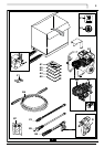
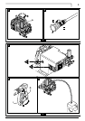
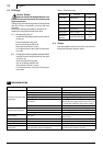
The supply package is illustrated in fig.1
1.2.1 Documentation supplied with the appliance
A1 Use and maintenance manual
A2 Safety instructions
A3 Declaration of conformity
A4 Technical data
A5 Engine instruction manual
1.3 Disposing of packaging
The packaging material must be disposed of in accord-
ance with the relevant legal requirements.
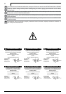
1.4 Safety signs
Comply with the instructions provided by the safety
signs fitted to the cleaner.
Check that they are present and legible; otherwise, fit
replacements in the original positions.
E1 sign - indicates that the cleaner must not be dis-
posed of as municipal waste; it may be handed in to the
dealer on purchase of a new cleaner.
The cleaner’s electrical and electronic parts must not be
reused for improper uses since they contain substances
which constitute health hazards.
E2 sign - indicates that ear defenders must be worn.
2
TECHNICAL INFORMATION FIG. 1
2.1 Envisaged use
This appliance has been designed for individual and
professional use for the cleaning of vehicles, machines,
boats, masonry, etc, to remove stubborn dirt using clean
water and biodegradable chemical detergents.
Vehicle engines may be washed only if the dirty water is
disposed of as per regulations in force.
- Intake water temperature: below 60 °C.
- Intake water pressure: below 10 bar.
- Operating ambient temperature: above 0 °C.
The power-jet cleaner is compliant with the 98/37/EC
Directive.
2.2 Operator
Use of the cleaner requires specific technical skill and
training and a good sense of responsibility.
The operator must meet specific physical and mental
requirements to be suitable for the job in hand; the clean-
er must therefore only be used by the appointed person.
2.3 Improper use
Use by unskilled persons or those who have not read
and understood the instructions in the manual is for-
bidden.
The introduction of inflammable, explosive and toxic
liquids into the cleaner is prohibited.
Use of the cleaner in a potentially inflammable or explo-
sive atmosphere is forbidden.
The use of non-original accessories and any other
accessories not specifically intended for the model in
question is prohibited.
All modifications to the cleaner are prohibited. Any
modifications made to the appliance shall render the
Declaration of Conformity null and void and relieve the
manufacturer of all liability under civil and criminal law.
2.4 Main components
B1 - Engine
B2 - Reduction gearbox (where fitted)
B3 - Pump
B4 - Gun with safety catch
B5 - Lance
B6 - High pressure hose
B7 - Oil caps
2.4.1 Accessories
C1 Nozzle cleaning tool
C2 Rotopower (where fitted)
2.5 Technical data
The technical data are specified in the enclosure.
2.6 Safety devices
Caution - Danger!
Never tamper with the safety devices.
- Safety valve and pressure limiting valve
The safety valve is also a pressure limiting valve. When
the gun trigger is released, the valve opens and the
water recirculates through the pump inlet.
- Thermostat valve (D1)
If the water temperature exceeds the temperature set
by the manufacturer, the thermostat valve discharges
the hot water and draws in an amount of cold water
equal to the amount of water discharged.
- Safety catch
(D): prevents accidental spraying of water.
2.7 Noise levels
At even short exposure times, noise may cause hearing
impairment in the long term.
Users must wear ear defenders to protect their
hearing.
3
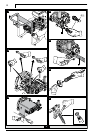
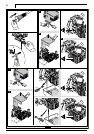
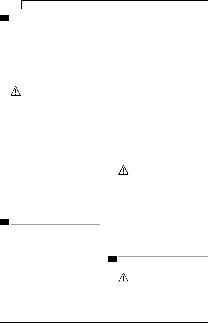
INSTALLATION FIG. 2
3.1. Assembly
Caution - Danger!
All installation and assembly operations must
be performed with the engine off.
The assembly sequence is illustrated in fig. 2.
3.2 Fitting the pressure release caps
To prevent oil leaks, the appliance is delivered with the
oil intakes sealed with red caps which must be replaced
with the pressure release caps supplied.
English10