


2
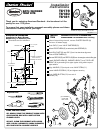
TO GAIN ACCESS TO VALVE FOR SERVICING
Remove CARTRIDGE (1) by removing CARTRIDGE SCREWS (2). Remove three
SCREWS (3) from FIXATION RING (4) and pull out PRESSURE BALANCING (5) unit.
Clean SEALS (9) on base of CARTRIDGE (1). Check base of PRESSURE BALANCING
UNIT (5) and clean O-RINGS (6). Remove CAPS (7) and check O-RINGS on inside
of CAPS (7) for debris. Clean inside sealing surfaces of VALVE BODY (8).
Re-assemble PRESSURE BALANCING UNIT (5) and CARTRIDGE (1). Tighten all screws.
Turn on water supply and see above for installing TRIM and HANDLE. If it still leaks, replace
pressure balancing unit (M952100-0070A).
VALVE LEAKS WHEN SHUT OFF
BACK TO BACK INSTALLATION
Remove PRESSURE BALANCE UNIT (5).
Remove CAPS (7) and clean valve thoroughly.
Examine balancing unit and check condition of O-ring on end of piston. Piston should move back and forth. Order Repair
Part M952100-0070A if balancing unit is defective.
Replace CAPS (7) and install PRESSURE BALANCE UNIT (5). Make sure inlets line up with two holes in bottom of casting.
Top flange should butt-up against top of casting.
Remove PRESSURE BALANCE UNIT (5). Rotate PRESSURE BALANCE UNIT (5) 180˚ so that the inlets face up and the
large outlet port faces down.
Push PRESSURE BALANCE UNIT (5) in casting make sure inlets line up with holes in bottom of casting. Top flange should
butt up against top of casting. Reassemble FIXATION RING (4) and CARTRIDGE (1).
UNABLE TO MAINTAIN CONSTANT TEMPERATURE
BACK TO BACK INSTALLATION
ROTATE 180
˚
1
2
9
5
5
7
8
6
4
3
INLETS
LARGE OUTLET
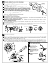
ADJUST HOT LIMIT STOP
By restricting HANDLE rotation and limiting the amount of hot water allowed to mix with the cold, the HOT LIMIT SAFETY
STOP (1) reduces risk of accidental scalding. To set the maximum hot water temperature of your faucet, all you need to
do is adjust the setting on the HOT LIMIT SAFETY STOP (1).
1
5
1
3
1
1
9
7
5
3
1
0
1
5
1
3
1
1
9
7
5
3
1
1
5
1
3
1
1
9
7
5
3
1
3
COLDER
(Larger Numbers)
0 1 3 5 7 9 11 13 15
HOTTER
(Smaller Numbers)
0 1 3 5 7 9 11 13 15
Turn CARTRIDGE STEM (2) to the OFF position (coldest setting) before making adjustment to HOT LIMIT STOP (1). Use a
flat blade screwdriver to pry free the HOT LIMIT SAFETY STOP (1). Pull forward and rotate counterclockwise one number
to limit hot water temperature. Use ARROW (3) on CARTRIDGE (4) and NUMBERS (5) on HOT LIMIT STOP (1) for indication.
1
5
1
5
4
4
3
3
2
2
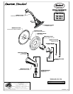
TEST INSTALLED FITTING
4
Turn VALVE (1) "off".
With HANDLE (2) in "off"
position, turn on water
supplies and check
all connections for leaks.
Operate HANDLE (2) and flush
water lines thoroughly. Pull
DIVERTER (3) up and check
SHOWER (4) for proper
operation.
Check SPOUT (5) and
SHOWER (4) connections
for leaks.
1
2
3
5
4
M968411A
HANDLE
and TRIM
Remove HANDLE and TRIM. See step one and reverse assembly
procedure.