


1
753737-100 Rev. C
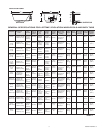
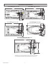
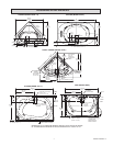
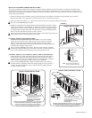
For 6060L/V Corner Only
OPERATION
ELECTRICAL CONNECTIONS
Install a separate 10VAC / 15AMP dedicated circuit with GFCI (Ground Fault Circuit Interrupter) protection.
At initial start-up with power ON, push the GFCI test button. The reset button should pop out. Push this button in to reset. If the GFCI fails to
operate in this manner, there is a ground fault or malfunction, indicating the possibility of electrical shock. Turn off the power and do not
use the bath until the source of the problem has been identified and corrected.
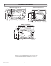
1. Route two separate branch circuits to the junction box near the whirlpool as shown in Figure . Each branch circuit MUST BE GFCI
PROTECTED and must use copper conductors only.
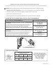
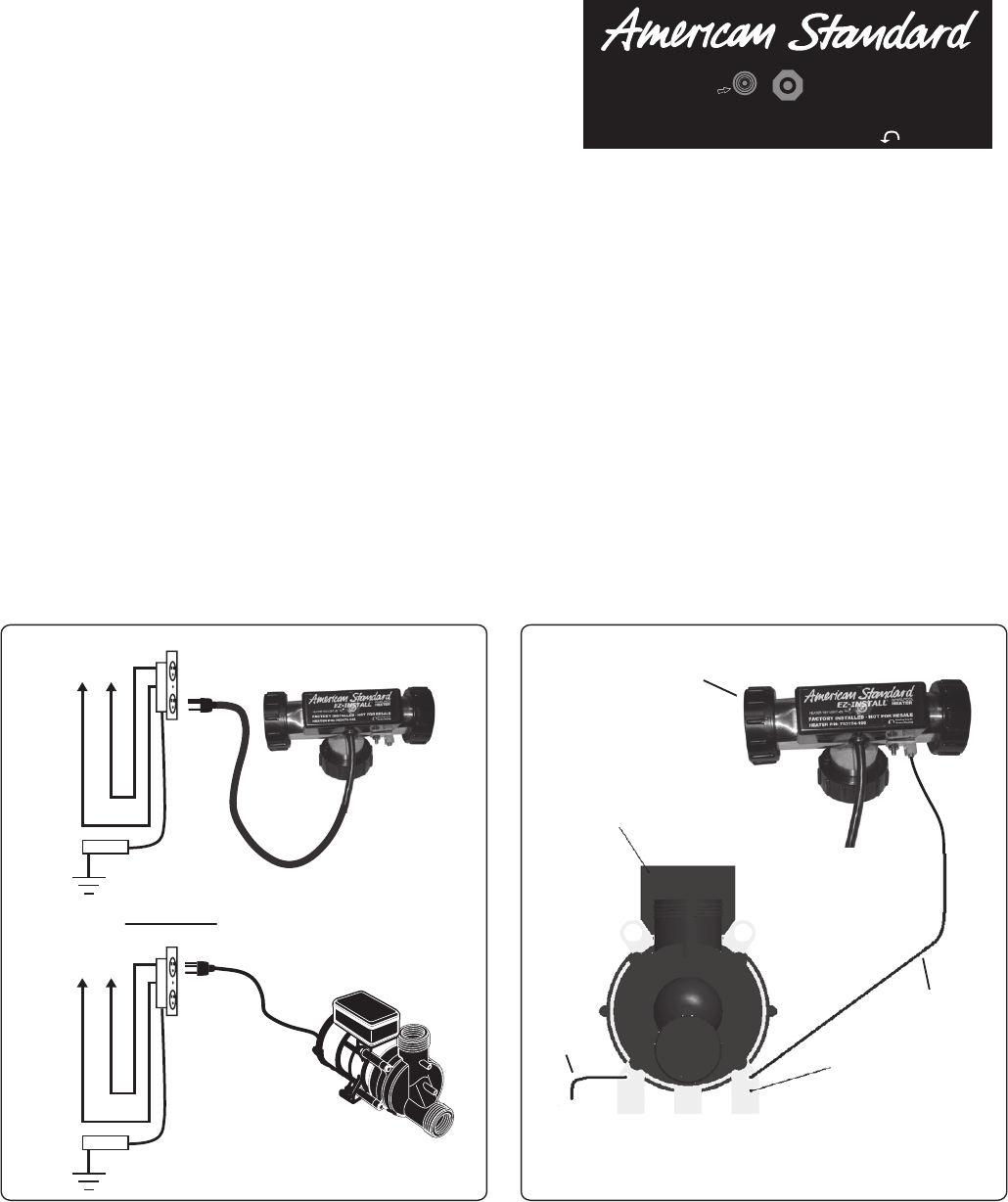
. Ensure the heater and pump are properly GROUNDED and BONDED as required. Attach the AWG solid copper conductor supplied with
the heater from the heater bonding lug to the motor frame bonding lug as shown in Figure 3. The conductor is secured to the lugs using set
screws. The motor frame shall have a second AWG solid copper conductor connected from the frame bonding lug to the homes electrical
panel or approved local bonding point as shown in Figure 3.
Fig. 2 Fig. 3
Fig. 1
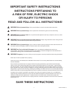
WARNING: Prior to operation, review the Important Safety Instructions
listed at the beginning of this instruction manual.
Once the heater is installed and the whirlpool pump is operating, the heater is
totally automatic. The heater will help maintain the temperature of the water in
the bath.
Pressure Switch
The heater is equipped with a preset pressure switch. The pump must be
running with water flowing in the whirlpool to allow the heater to turn on.
Indicator Light
This light turns on whenever the heater is operating.
High-Limit Switch
The heater includes an exclusive "Intelligent High-Limit". This safety circuit will not "false trip" from hot tap water. It will only turn the heater
off if the thermostat fails. If the high-limit trips frequently, call a service technician.
To manually reset the circuit in the event that the “High-Limit” switch has been activated, simply (1) Turn off the whirlpool pump. () Drain
water from the tub. (3) Remove power from heater by unplugging at receptacle or turning off circuit breaker. () The heater circuit will
automatically reset in less than 15 minutes. (5) Restore power to the heater. () Whirlpool bath is now ready to use.
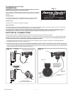
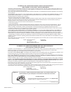
ELECTRICAL DIAGRAM
READ AND FOLLOW ALL INSTRUCTIONS
BLACK
WHITE
120 VAC
GND.
SEPARATE 20 AMP GFCI OUTLET
for2.1 H.P. PUMP
SEPARATE 15 AMP GFCI OUTLET
for 1.6 H.P. PUMP
PUMP/MOTOR
ELECTRICAL INSTALLATION
HEATER
BLACK
WHITE
120 VAC
GND.
SEPARATE
15 AMP GFCI OUTLET
HEATER “ON” LIGHT
Bonding Lug on
Heater Housing
E-Z INST
AL
L
™
WHIRLPOOL
HEA
TE
R
RUN AWG SOLID COPPER
CONDUCTORS FROM
HEATER BONDING LUG TO
PUMP/MOTOR FRAME LUG
AND FROM PUMP/MOTOR
LUG TO APPROVED
GROUND AS SHOWN
(PUMP/MOTOR)
TO GROUND
SECOND
COPPER
CONDUCTOR
FIRST COPPER
CONDUCTOR
PUMP/MOTOR FRAME WITH
BONDING LUGS
HEATER ON
E-
Z
IN
S
TA
L
L
™
W
H
IR
L
P
O
O
L
HE
AT
ER
FACTORY INSTALLED - NOT FOR RESALE
HEATER P/N: 753174-100
(HEATER)