


INSTALLATION INSTRUCTIONS
THANK YOU...
for selecting an American Standard bath. Your new bath is shipped to
you after careful inspection. the whirlpool version is completely
assembled with pump, motor, and system piping. All you need to finish
the installation are your selected fittings and electrical connections for
a whirlpool. To insure maximum performance and pleasure from this
product, please follow the instructions and cautions.
General Installation Information
Carefully uncrate and inspect your new bath for any shipping damage.
If such damage is found, report it to your vendor immediately. After
inspection and during installation, protect the bath from construction
damage. Before installation, and before enclosing with wallboard,
tile, etc., water test the unit and check for leaks. Do not make
modifications to the whirlpool system or remove pump from factory
mounting. This could adversely affect the safety and performance of
the whirlpool and void the warranty. Do not handle or move the
whirlpool by the pump, motor, or piping system. Fittings (bath filler,
shower arm, etc.) are not provided with the bath and must be ordered
separately. Framing and enclosing materials are provided by others.
753572-100
© American Standard Inc. 2004
All product names listed herein are trademarks
of American Standard Inc. unless otherwise noted.
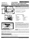
INTEGRAL APRON WITH
REMOVABLE ACCESS PANEL
HIGH GLOSS ACRYLIC
SHOWN LESS ALL FITTINGS
COLONY™ 5'
1749 SERIES
WHIRLPOOL/BATHING POOL
FOR AFTER-SALES SERVICE CALL 1 (800) 442-1902 WEEKDAYS.
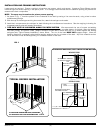
General Installation Information
Bath may only be installed in a recess type installation.
Locate studs as required. insure rough dimensions are proper, plumb and square. For whirlpools, access to pump/motor may be made
through access opening in apron panel. The following procedure must be used for all installations: leveling support stringer should be as
indicated. this bath is not self-supporting and must be supported along it's entire bottom. Support with mortar or grout. Position
bathtub/whirlpool within the recess, check level, front to back, side to side, and shim as necessary. To secure the tub to wood studs use
drywall screws w/washers or roofing nails immediately above the flange of the tub. To secure the tub to steel studs use 4" drywall screws and
flatwashers.
See page 2 for complete installation information.
Caution: Take extra care when driving nails or screws to avoid damaging the tub. The tile or similar finished floor will be butted against
the bottom of the tub apron, also holding the tub in place.
IMPORTANT: Water test unit before installation and
enclosure!
List of Required Components (not included):
• Drain 1583.470* • Bath Filler*
* see your American Standard Dealer
List of Required Tools and Supplies:
Tools
• Level
• Tape Measure
• Pipe Wrench
• Slip Joint Pliers
• Screw Driver
• Standard
Woodworking Tools
• Personal Safety
Equipment
• Caulking Gun
Supplies
• Nails
• Putty
• Caulking (waterproof)
• 1 x 3 or 2 x 2
Stringers
• Drop Cloth
• 15 amp GFI
Outlet
• Cement, Plaster,
Grout
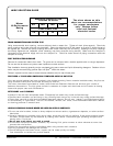
GENERAL SPECIFICATIONS FOR 1749 WHIRLPOOL
60 x 42 x 19 In.(1525 x 1067 x 483mm)
112 Lbs. (50 Kg.)
714 Lbs. (324 Kg.)
72 Gal. (274 L)
52 Gal. (197 L)
44 x 23 In. (1120 x 585mm)
54 x 26 In. (1370 x 660mm)
13-5/8 In. (346mm)
41 Lbs./Sq.Ft. (193 Kgs./Sq.m)
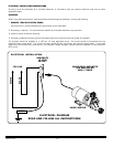
WHIRLPOOL ELECTRICAL SPECIFICATIONS
1.0 HP, 9.9 AMPS, 120V.PUMP
INSTALLED SIZE
WEIGHT
WEIGHT w/WATER
GAL. TO OVERFLOW
WHIRLPOOL MIN. OPERATING VOL.
BATHING WELL AT SUMP
BATHING WELL AT RIM
WATER DEPTH TO OVERFLOW
FLOOR LOADING
(PROJECTED AREA)
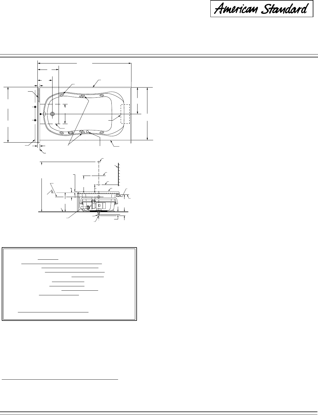
60"
(1524 mm)
12"
(305 mm)
8-3/4"
(222 mm)
9"
(229 mm)
2-3/4"
(70 mm)
CUTOUT IN FLOOR FOR DRAIN
(6) JETS
(2) AIR VALVES
ACCESS TO PUMP/MOTOR
THROUGH REMOVABLE
FRONT ACCESS PANEL
ON/OFF
SWITCH
WATER RETENTION
FLANGE (3 SIDES)
C/L OF DRAIN
3/4"
(19 mm)
43-1/2"
(1105 mm)
42"
(1067 mm)
21"
(535 mm)
PUMP
FINISHED
WALL
C/L OF
SUPPLIES
SEE FITTING
SPECS FOR
DIMENSIONS
18-1/2
(470mm)
REF.
DIM
1-1/4" WATER
RETENTION
FLANGE
(3 SIDES
& APRON)
19
(485mm)
1-1/2 O.D.TAILPIECE
BATH
SUPPORT
MATERIAL
LEVELING
STRINGER
NOT FOR
SUPPORT
ROUGH
FLOOR
FINISHED
WALL
TOP OF
DECK
2-3/4
(70mm)
12
(305mm)
OPT.
OPTIONAL TO
FINISHED FLOOR
USUALLY BETWEEN
65 & 78
(1651 & 1981mm)
C/L OF
OVERFLOW
4
(102 mm)
C/L OF
SPOUT
TILING
FLANGE
C/L OF
VALVES
C/L OF
SHOWER ARM
2-3/4
(70mm)
4-5/8
(117mm)
1-1/2 N.P.T.M.
THREADS
UNDERSIDE
OF DECK