


ASSEMBLY
SL72 03/08 Assembly Section 3-3
© 2008 Alamo Group Inc.
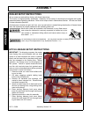
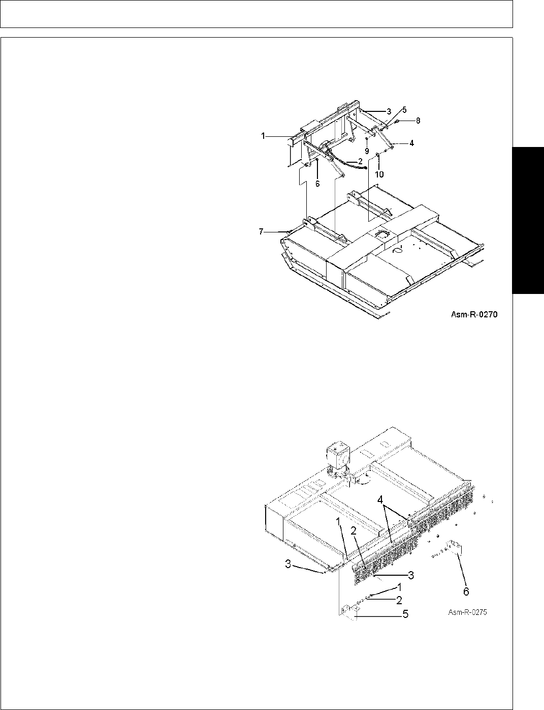
ASSEMBLY
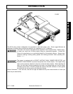
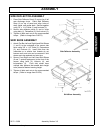
HITCH ASSEMBLY
1. Secure Hitch Weldment (1) to mower deck
using 1" x 5" Bolts (7) and 1" Locknuts (6).
2. Insert Bushing (5) in upper holes of hitch
weldment, place a set of Upper Floating Links
(3) on each side of bushing, and secure
together using 5/8" x 1-3/4" Bolt (8) and 5/8"
Locknuts (9). Place bushing (5) between
opposite upper floating link set ends and secure
pairs together with bolt (8) and locknut (9).
3. Place bushing (5) into end of Lower Floating
Links (4) and secure between upper links with
bolt (8) and locknut (9). Place another bushing
into opposite lower link hole and place against
outside of lugs near center of mower deck.
Insert bolt (8) through link, bushing, and lug,
and retain together with 5/8" Flat Washer (10),
and locknut (9). Hitch weldment is installed on
mower when shipped from factory. Reposition
floating link bushing from storage/shipping
position to operating position as outlined on
page 3-2.
4. Secure Safety Chain (2) around lower hitch
frame.
5. Tighten all bolts and nuts to the recommended
torque. (Refer to Image Asm-R-2070)
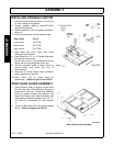
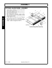
FRONT CHAIN GUARD ASSEMBLY
1. Attach Front Chain Guard Bracket (4) to Front
of Deck using 1/2" x 1-1/4" Bolts (1), 1/2"
Flatwashers (2), and 1/2" Locknuts (3).
2. Attach the Right and Left Side Shields (5 and 6)
to deck sides using bolts (1), flatwashers (2),
and locknuts (3).
3. Tighten all bolts and nuts to the recommended
torque. (Refer to Image Asm-R-0275)
Hitch Assembly
Front Chain Guard Assembly