


ASSEMBLY
SHD 03/09 Assembly Section 3-7
© 2009 Alamo Group Inc.
ASSEMBLY
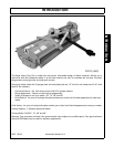
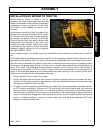
INSTALLATION OF MOWER TO TRACTOR
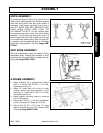
Before attaching mower to tractor, it will be
necessary that each tractor lower hitch arm has
freedom of movement that the mower is completely
independent of tractor movement. This will allow
the mower to pivot sideways as well as move
vertically.
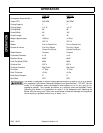
Some tractors provide this “float” by means of an
optional slot in the lower end of each lift link, others
by lift check chains which can be made telescopic
by changing the position of the pins in the links.
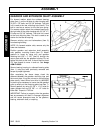
Failure to provide “float” may result in failure of the
cutterhousing and bearings in the roller, thus
voiding the mower warranty. Should your tractor
not have built a “float” option, a flexible check chain
assembly (optional equipment) will be required.
See Figure ASMP-FL-0019.
On all centered mowers, two flexible check chain assemblies will be necessary to provide “float” to each lift
link.
On all offset mowers, one flexible check chain assembly will be necessary to provide “float” to the lift link on the
same side that the mower is offset. The other lift link should be the adjustable stiff link furnished with the tractor.
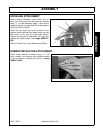
After the mower is attached to the tractor’s 3 point hitch, but before the universal slip joint is installed, and with
the mower on the ground, adjust the top link of the hitch to make the mower gearbox input shaft parallel to the
tractor P.T.O. shaft. This relationship provides optimum operation of the universal joints in the driveline. A
Driveline that is not parallel to PTO will result in vibration due to the characteristic of a universal joint that
results in the output end speeding up and slowing down twice each revolution of the universal jointed chart.
Adjust the top link whenever the cutting height is changed.
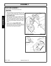
1. Position the SHD Flail on a level, firm surface.
2. Position the tractor so that the lower hitch arms are level with and slightly ahead of the mower over arms.
Carefully inch the tractor rearward to align the tractor hitch arms between the mower hitch over arms. Stop
the engine and insert the lower hitch pins.
3. To install the driveline separate slip joint halves, then install them onto mower gearbox input shaft and trac-
tor PTO driveline according to illustration on PTO shaft shield. Hold halves side by side, then raise and
lower the mower to determine that there is no interference between halves when in the shortest position,
and that there is a specified minimum amount of overlap when in the longest position. Always maintain at
least 6” of driveline tube engagement when operating the mower. Once it is determined that the shaft will
cause no clearance problems, remove the halves, rejoin them and install the assembled PTO shaft
between the tractor and the mower.