


© 2005 Alamo Group Inc.
Section 7 - 11
Switch Blade (JD-5105-5205-5225-5325-5425-5525, Asy. Man) 05/05
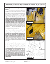
CARRIAGE ARM ASSEMBLY REPLACEMENT
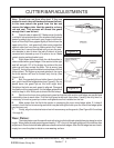
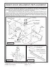
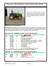
Carriage Arm Assembly Replace-
ment:
The carriage arm replacement will require
the Back Pivot Plate to be unbolted with the skid
shoe / break-a-way assembly to be removed with
Back Pivot but not disassembled. The skid shoe /
break-a-way assembly can be removed by unbolt-
ing the back pivot plate from the carriage arm (See
Figure 17 thru 25). The hydraulic hoses to the
motor will not have to be disconnected but the hose
brackets may have to be disconnected to allow the
assembly to be moved outward far enough to clear
carriage arm assembly. If the complete cutterbar /
break-a-way assembly needs to be moved it is
sometimes easier and cleaner to unbolt the motor
and the complete assembly can be removed an the
motor can be moved out of the way with the hoses
attached to it. DO NOT pull assembly with the
hoses attached and damage them.
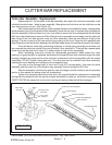
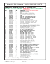
To remove the carriage arm the lift and tilt
cylinder will need to be disconnected, the hoses will
not require disconnecting, the cylinders can be set
aside with the hoses connected. Remove the roll
pins from the carriage pin. The carriage arm is
pinned to the back pivot plate and the tractor main-
frame. The mounting frame to attach to the tractor
will vary from tractor model, but the way the car-
riage arm is pinned to will not. Drive the carriage
pins out and carriage arm will lift out (See Figure 24,
25 & 26).
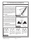
To reassemble the carriage arm reverse
the disassembly instruction, insert carriage arm,
insert carriage arm pins, install roll pin in to carriage
arm pin. Install the lift and tilt cylinders, make certain
hoses connecting to the cylinders is not twisted or
routed wrong as they could be damaged. Attach the
back pivot plate with the carriage pin. Bolt the
cutterbar / skid shoe assembly to the back pivot
plate, note the two lower holes in back pivot plate
are slotted on a curve. Flatwashers will have to be
used on these two lower bolts (See Figure 25). The
pitch of the cutter bar will have to be readjusted, see
pitch adjustment instructions in earlier pages (See
Figure 4 & 26)
Carriage Arm
Assembly
Back Pivot
Plate
Inner Shoe
Wledment
Figure 24
Figure 25
Figure 26
Carriage Arm
Assembly
Carriage Arm
Pin
Back Pivot
Plate
Carriage Pin
Carriage Pin
Carriage Arm
Rear View
Front View
Curb Lift Cyl.
Bar Tilt
Cyl