


© 2005 Alamo Group Inc.
Section 3 - 7
Switch Blade (JD-5105-5205-5225-5325-5425-5525, Asy. Man) 05/05
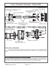
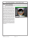
Pump & Drive Shaft Installation:
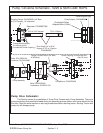
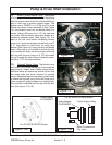
A. Find the front from the rear of cover.
B. Mark a half circle as shown in figure 9.
C. This half circle should be a minimum
of 3 inches deep and 5 inches wide
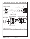
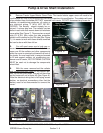
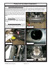
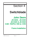
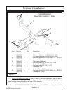
8. Cut Bolster Cover Plate. Make certain that
the Engine end of cover is cut. How you cut this is
the technicians choice, we recommend a torch or
a plasma cutter (See Figure 10). After the half
circle is cut out of cover, use a grinder to clean the
edges to eliminate any sharp edges (See Figure
11). After Cover has been cut and cut edges
cleaned up set cover aside for now.
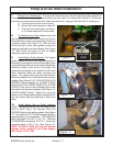
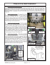
9. Install Engine Pulley Adapter. The Engine
pulley adapter will bolt to the crankshaft pulley of
the tractor. Looking at the front of the engine at the
crankshaft pulley there are four bolts and washers
retaining a plate to the front of the pulley, this
spacer comes already on the tractor but will not be
used. Remove these four bolts removing the
spacer. The spacer will not be used but the four
bolts and washers will. Install the furnished pulley
adapter (See Figure 12 & 13 P/N 02973992 & P/N
02702900 splined adapter for JD-5425 & 5525)
(See Figure 13A & 13B P/N 02982837 for JD-5225
& 5325) to the front of the crankshaft pulley with
the tractor four bolts and washers (See Figure 12,
JD-5425 &-5525 Shown). Tighten the four bolts
down to John Deere specifications as specified in
the John deere Manual pertaining to these four
bolts.
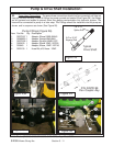
10. Install Spline Hub to Pulley Adapter.
NOTE; This spline bolt on hub will apply to JD-
5425 & 5525 Only). The Splined Hub (P/N
02702900) bolts to the pulley adapter (See Figure
13). The Hub has 7/8" X 13 Spline center with four
mounting bolts & Lockwashers (P/N 02976344
Bolt, Hex Head 7/16"-NC X 1-1/4" - PL - GR8 and
P/N 00022200 Lockwasher 7/16" PL). Torque the
mounting bolts to 65 ft. lbs. (See Figure 13).
NOTE: JD-5225 & 5325 will have the splined
adapter sleeve welded to the Pulley adapter
(See Figure 13A & 13B).
TOP
FRONT END
Figure 9
Cut Out
Here
ENGINE
END
Figure 10
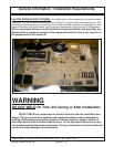
7. Bolster Cover Modification. The cover will have to be cut, this is to allow the pulley adapter for
the drive shaft clearance. Lay the cover where you can mark it for cutting (See Figure 9). This shows
the cover turned around from the way it was removed and is laying on the front tire for marking cut.
Figure 11