ASSEMBLY
Eagle 20 03/09 Assembly Section 3-6
© 2009 Alamo Group Inc.
ASSEMBLY
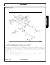
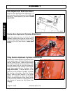
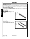
Axle Adjustment Rod Attachment
Attach the Axle Adjustment Rod w/Bushings (1) to
the Center Axle (2) and Wing Axle (3) with bolts and
locknuts (4). Install Spacers (5) as shown. FIGURE
Asm-R-0018.
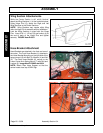
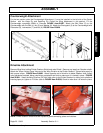
Center Axle Hydraulic Cylinder Attachment
Install the clevis rod end (1) of the 8" stroke
Hydraulic Cylinder to the lug on the Center Axle (2).
The clevis base fastens between the flats on Spring
Assembly (3) on the Center Section. Image AsmP-
R-0005.
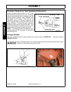
Wing Section Hydraulic Cylinder Attachment
Mount the 14" stroke Hydraulic Cylinder butt clevis
to the upright lugs on the Center Section and the
rod end to lugs on wing. Make sure the ports of
the Hydraulic Cylinder are facing upwards. Keep
the ports capped until the hoses are attached to
the tractor and are ready to attach to the cylinder
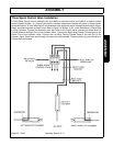
ports. Make certain that the Restrictor ,(A) in
Image Asm-R-0019, is installed properly on the
gland end of the Hydraulic Cylinders to prevent
fast lowering of the wings. Install the Transport
Bars to retain the Wing Sections in the upright
position for transport on roads and highways.
When in transport keep the Center Section as low
to the ground as possible to increase stability but
high enough to prevent the Skid Shoes from
dragging.


