A-Boom (JD 6615 / 7615 Asy Instruction Manual) 07/03
© 2003 Alamo Group Inc.
Section 4 - 6
High Frame Installation
Frame Rail Pre-Assembly: (continued)
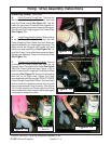
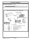
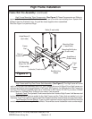
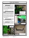
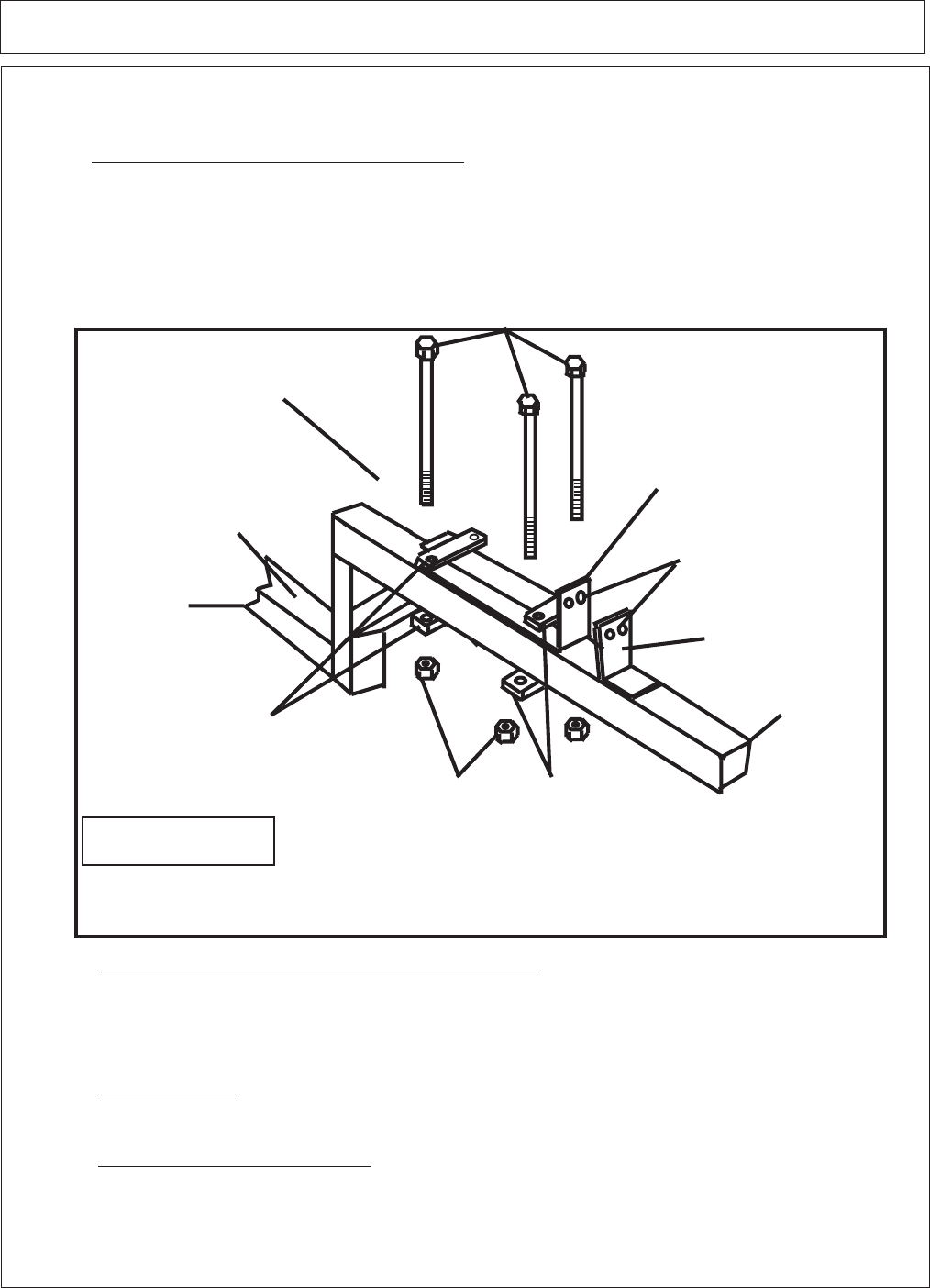
High Frame Mounting Tube Components. (See Figure 4) These Components are Sitting in
approx. position of assembly to illustrate where they are to be when tack welding them. Space is left
between them for Illustration only, they will be closer together when assembled.
Also See Figure 3 on previous Page.
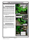
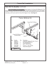
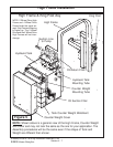
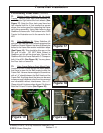
High Frame and King Post Frame Sub-Assembly. (See Figure 5) The High frame will come
with the King Post Sub-Assembly built to it. The 2 Wheel drive and 4 Wheel Drive High frames are
different and will not interchange between 2 WD and 4 WD Tractors, the 4 Wheel drive High Frame has
the King Post Mounting welded higher up on frame than 2 WD Frame. DO NOT try to use a 2 Wheel
drive Frame on 4 Wheel Drive Tractor or vice versa, it will not work.
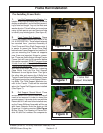
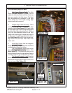
Hydraulic Tank, The Hydraulic Tank is mounted on the LH side of High Frame. It will be mounted
by the Mounting tubes that are welded to the High Frame and the Tubes that are welded on to the
Hydraulic Tank. There will be long bolts with Allen Heads that will be inserted down through these tubes.
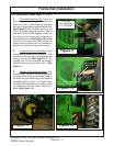
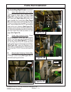
Tank Mounted Counter Weight. There is a tank mounted counter weight that will be mounted
on to the Hydraulic Tank useing Allen Head Bolts. There will be a cover that bolts on over counter weight.
Frame
Rail
Mounting Tube
(1 each side)
Angle Mount
(2 each side)
Bolts (3 each side)
Locknuts (3 each side)
Angle Mount (2
each side)
Mounting Bolt Holes
(2 each end)
Bar Mounting
Straps
Rear of
Frame Rail
Front
of
Frame
Rail
Figure 4
Bar Mounting
Strap Cut Off
(2 each side)


