5
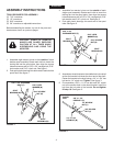
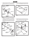
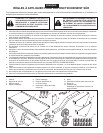
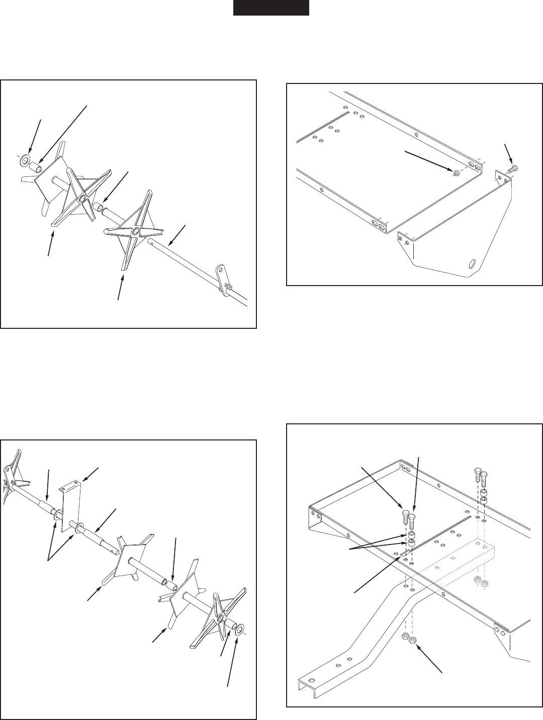
7. Assemble a single spool assembly, a 1" long spacer, a
double spool assembly, a 1.33" long spacer and a 3/4"
atwasherontotheshortendoftheshaft.Seegure
4.
FIGURE 5
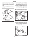
9. Assemble an end plate to the end of the tray using four
5/16" x 3/4" hex bolts and four 5/16" nylock nuts. Repeat
for other end. Do not tighten till step 20.Seegure
6.
FIGURE 6
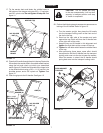
FIGURE 7
8. Assemblea2.38"longspacer,a3/4"atwasher,the
middlebrace,a3/4"atwasher,a3.70"longspacer,
a single spool assembly, a 1.33" long spacer, a double
spoolassembly,a1.33" longspacerand a3/4"at
washer onto the long end of the shaft. The bent lip of
the middle brace must face the short end of the shaft.
Seegure5.
FIGURE 4
10. Assemble the tongue to the tray, placing the slot's lock-
ing notch to the front. Use two 3/8" x 1" hex bolts, two
3/8" x 1-1/4" hex bolts, four 1/4" long spacers, and four
3/8"nylocknutsasshowningure7.Tighten.
SINGLE SPOOL
ASSEMBLY
DOUBLE SPOOL
ASSEMBLY
1" LONG
SPACER (S)
1.33" LONG
SPACER (T)
3/4" FLAT
WASHER (O)
SHORT END
2.38" LONG
SPACER (Q)
1.33" LONG
SPACER (T)
1.33" LONG
SPACER (T)
3/4" FLAT
WASHER (O)
MIDDLE
BRACE
3.70" LONG
SPACER (R)
3/4" FLAT
WASHER (O)
SINGLE SPOOL
ASSEMBLY
DOUBLE SPOOL
ASSEMBLY
3/8" x 1"
HEX BOLT (D)
3/8" x 1-1/4"
HEX BOLT (C)
1/4" LONG
SPACERS (P)
3/8" NYLOCK
NUT (J)
LOCKING
NOTCH
5/16" x 3/4"
HEX BOLT (E)
5/16" NYLOCK
NUT (K)
ENGLISH


