


Replaceable Parts
Assembly and Disassembly Guidelines
Agilent E4418B/E4419B Service Guide 5-23
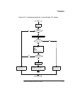
Replacing The Chassis Assembly
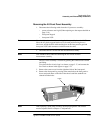
1. Remove the Power Meter Cover as shown in “Removing the Power Meter
Cover”, on page 5-8.
2. Disassemble the power meter down to allow access to the rear panel
connectors (Refer to “Removing the A4 Comms Assembly”, on page 5-11).
3. For Standard or Option #002 units, disconnect the Power Reference Cable
from the Front Panel Assembly.
4. For Option #003 units, disconnect the Power Reference Cable from the
Chassis Assembly (rear panel).
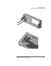
5. Remove the A3 Front Panel Assembly as shown in “Removing the A3 Front
Panel Assembly”, on page 5-15.
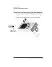
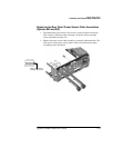
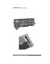
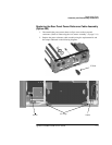
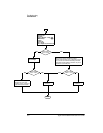
6. For Option #002 or Option #003 units, remove the Rear Panel Power Sensor
Cable Assemblies as shown in “Replacing the Rear Panel Power Sensor
Cable Assemblies (Options 002 and 003)”, on page 5-19.
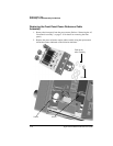
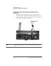
7. For Option #003 units, remove the Rear Panel Power Reference Connector
as shown in “Replacing the Rear Panel Power Reference Cable Assembly
(Option 003)”, on page 5-21.
8. Remove the Recorder Output(s) Cable Assembly as shown on page 5-21.
9. Remove all blanking plugs from the rear panel.
10. Obtain the new Chassis Assembly, and then re-assemble the Power Meter by
following steps 1 to 9 in reverse order.
WARNING When replacing the power supply unit in the power meter ensure that
all earth wiring is reconnected. There are two terminals to check, the
first is the force fit connector to the power supply unit itself and the
second a closed loop terminal bonded to the chassis with an M3.5
machine screw (use a 9 lb/in T15 screw driver). All the protective earth
wiring can be identified by the insulation color green with a yellow
stripe.
WARNING Once re-assembly is complete, the unit must be safety-tested in
accordance with local guidelines & procedures. This safety-test may
take the form of an Earth Continuity Test, Hi-Pot Test, etc.