Service Addendum44
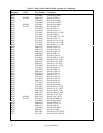
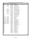
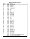
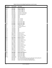
Table 6-3. Test Points (continued)
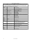
Test Point Signal Measurement and Conditions
The measurements at test points 26 through 39 were taken with full scale voltage
and full scale current programmed. The measurements were made first in the CV mode with no load and
then in the CC mode with the load set for full-scale output voltage and current. If the CC annunciator is
not on, set the current to a slightly lower value until it comes on.
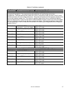
TP26 D413
cathode
CC control (sheet 2) 1.57V in CV mode
0.15V in CC mode
TP27 R703 RmOUTB (sheet 2) 3.3mV in CV mode with no load
0.19V in CC mode with 8A load
TP28 U403-7 Imon (sheet 2) 0.9mV in CV mode with no load
4.39V in CC mode with 8A load
TP29 R430 Neg Imon(sheet 2) 13.9mV in CV mode
-3.9V in CC mode with 8A load
TP31 U407-7 CC* (sheet 2) 5V in CV mode
0V on CC mode
TP32 U408-7 CV control (sheet 2) -0.8V in CV mode
1.55V in CC mode
TP33 U401-7 Vmon (sheet 2) 4.1V in CV or CC mode (@ full scale voltage output)
TP34 U407-12 CV*(sheet 2) 0V in CV mode
5V in CC mode
TP35 U408-3 CV or CC control (sheet 2) 0.5V in CV mode
0.98V in CC mode
TP36 D429
anode
FET control (sheet 2) 0.05V in CV mode
0.98V in CC mode
TP37 D419
cathode
Gross current limit circuit
(sheet 2)
14.5V in CV or CC mode
TP38 D425
cathode
DP Control (sheet 2) 0.22V in CV mode
1.9V in CC mode
TP39 R444 OV_Prog (sheet 2) 5.17V @ full scale OV programmed
TP40 R706 Fan_Prog (sheet 1) 0.5V approximate @ low speed
3.2V approximate @ medium speed (4A output)
5V approximate @ high speed (8A output)
TP41 R453 OC_Prog (sheet 2) 4.6V (turn-on default)
TP42 U405-5 OV circuit (sheet 2) 4.5V with full scale voltage programmed
0V with zero volts programmed
TP43 U405-7 OV circuit (sheet 2) 5V (no OV condition)
TP44 R510 Therm HS(sheet 2) 3.2V with heatsink @23C (voltage decreases as
temperature increases)
TP45 D430
anode
OC circuit (sheet 2) 5V with no overcurrent condition
TP46 D407
cathode
OC circuit (sheet 2) 0.45V with no overcurrent condition
2.3V in OC Protect


