


WARNINGS:
•
To avoid fire, shock, and serious personal injury, follow all
instructions carefully. Read and save these instructions for
future reference.
•
Do not install or use this unit if any part is damaged or miss-
ing.
•
IMPORTANT!
Fan installation must be complete, including the
assembly of blades, before testing the remote control unit.
NOTICE:
1. This control is designed to operate only one ceiling fan with an
incandescent light kit.
SAFETY PRECAUTIONS:
2. This wall control is rated for a maximum (ceiling fan only) motor amp
of 1.0 at 120 volts, total (incandescent bulb only) wattage equaling 240
watt maximum.
3. Do not use with solid state ceiling fans.
4. The decorative housing (canopy) at the ceiling must be metal.
The metal housing acts as a protective cover for the Control Unit.
DO NOT USE WITH A NON-METALLIC HOUSING.
5. Only the remote unit should be used to change fan speeds. Do not use
the pull chain to change fan speeds after installation.
6. Make sure no bare wires are exposed outside of the connectors.
7. All wiring must conform to national and local electrical codes. If you
feel that you do not have enough electrical wiring knowledge or experi
-
ence, have your fan control installed by a licensed electrician.
Any
electrical work not described in this manual should be performed
by a licensed electrician.
8. Do not use water or detergents to clean the remote transmitter unit. A
dry dust cloth will be suitable for most cleaning.
9. Use of this control with some ceiling fans could result in fire, shock,
and serious personal injury. Use this fan control only with capacitor
speed controlled ceiling fans only.
B. INSTRUCTIONS FOR YOUR NEW WESTINGHOUSE REMOTE FAN CONTROL SYSTEM
WARNING: HIGH VOLTAGE
Before connecting this control unit:
• Disconnect electrical power from the circuit to be used.
• Household power can cause serious injury or death.
• Wiring must meet all local electrical code requirements.
NOTE: Before installing this
unit, change the factory code
switch setting to your own
preferred setting.
Be sure the code switch posi-
tions of the transmitter and
receiver match each other or
the ceiling fan will not function.
If this unit causes interfer-
ence with other appliances,
you may need to select
different combinations.
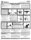
1. Setting the code on your new remote (see figure 6).
• Remove battery cover. Press firmly below arrow and slide battery cover off.
2. Slide code switches to your choice of UP and DOWN positions (use ball point
pen or small screwdriver to slide firmly up or down). Factory setting is all UP.
Do
NOT
use this setting.
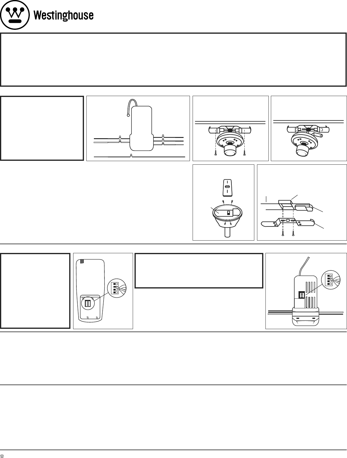
3. Setting the code on your new control unit (see figure 7).
• Slide code switches to the same positions as set on your REMOTE.
NOTE: The code switches on the transmitter and the receiver unit must be set to
the same positions to work.
WIRES
CODE SWITCHE
S
1 2 3 4
1 2 3 4
RECEIVER
(CONTROLLER UNIT)
WIRES
WIRES
FIGURE 7
TRANSMITTER
(BACK OF REMOTE)
CODE SWITCHE
S
1 2 3 4
1 2 3 4
FIGURE 6
A. MAKING THE ELECTRICAL CONNECTIONS:
NOTE: This remote only works
with some fans in sloped ceiling
model.
Do not use fan speed control in
canopies where the mounting is
not as described in figures 4 or 5.
This remote cannot be installed in a
downrod style fan when in flushmount
mode (when downrod is not in use).
1. Disconnect existing wiring between ceiling fan and AC sup-
ply at electrical junction box.
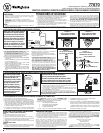
2.
FOR FANS ON A DOWNROD:
Remove ceiling fan canopy
from its mounting plate. Go to step 5.
FOR FLUSHMOUNT FANS:
Remove decorative housing
from mounting plate (see figure 2). Disconnect mounting
bracket from mounting plate and allow to hang from one side
(see figure 3).
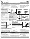
3. Making the electrical connection:
• Connect GREEN fan wire to BARE (ground) wire.
• Connect BLACK control unit wire to BLACK supply wire
(AC L).
• Connect WHITE control unit wire to WHITE supply wire
(AC N).
• Connect WHITE control unit wire (MOTOR N) to WHITE
fan wire.
• Push the connected wires up into the junction box.
Place
BLACK wires on one side of box, and WHITE, GREEN
and
BARE (ground) wires on the other side of the box.
•
Connect RED control unit wire (MOTOR L) to BLACK fan wire.
• Connect BLUE control unit wire (FOR LIGHT) to BLUE
light wire.
• Push the connected wires up into the junction box.
• Lay the BLACK control unit wire (ANTENNA) on top of the
control unit.
•
FOR FANS ON A DOWNROD:
Lay the control unit in the
canopy (see figure 4). Reinstall the canopy on its mount
-
ing plate. Restore electrical power to the circuit.
• FOR FLUSHMOUNT FANS:
Attach the control unit to
the mounting plate or to the ceiling with the supplied tie
wraps (see figure 5). Reconnect the mounting bracket to
the mounting plate (see figure 2). Reinstall the decorative
housing on its mounting plate. Restore electrical power to
the circuit.
NOTE: If the unit does not fit properly between the
mounting plate and ceiling, attach the unit to the
underside of the mounting plate.
BLACK BLACK
WHITE WHITE
BLUE
RED BLACK
WHITE WHITE
BLUE
CONTROL
UNIT
LIGHT
FAN
FAN
AC SUPPLY
AC SUPPLY
BARE (GROUND) GREEN FAN
AC SUPPLY
FIGURE 1
FIGURE - 2
FLUSHMOUNT FANS ONLY
FIGURE - 3
FLUSHMOUNT FANS ONLY
CONTROL
UNIT
FIGURE - 4
DOWNROD FANS ONLY
CEILING
JUNCTION BOX
MOUNTING PLATE
CONTROL UNIT
FIGURE - 5
FLUSHMOUNT FANS ONLY
TROUBLESHOOTING GUIDE
PROBLEM: REMOTE FAILS TO OPERATE
Check:
• Is there power to the control unit?
• Is the control unit wired correctly?
• Are the fan and light switches set on the highest position?
• Is there a good battery in the remote? If the red indicator lights when either
button is pushed, the battery is good.
•
Are the switches set the same in both the remote and the control unit?
PROBLEM: SHORT RANGE
Solution:
•
If the remote can operate the control unit when close to it but does not oper-
ate it at distances of 30-50 feet, try placing the black antenna wire above the
ceiling and outside of the junction box.
LIMITED WARRANTY
The Westinghouse remote control for ceiling fans offers a limited war-
ranty of one year from the date of purchase to the original owner against
defects in material and workmanship. All spare parts are covered for
ninety days only. This warranty is in lieu of all other warranties expressed or
implied.
Westinghouse will repair or replace this remote control if it is defec-
tive due to faulty materials or workmanship. This warranty does not cover
service charges, batteries, defects resulting from accidents, damages caused
through abuse or alterations or by affixing any attachment not provided with
the product, improper installation or maintenance, failure of supporting
devices not supplied as original mounting hardware, exposures to extremes
of heat or humidity, incorrect voltage, surges in current,
unauthorized repair, or failures caused by modifications of the product or the
acts of third parties. See remote manual for proper installation.
If a warranty claim is made in the first year, simply return the remote with
a copy of the original sales receipt, freight prepaid to Westinghouse Lighting
Corporation, who, at its option, shall repair or replace the remote or refund
the purchase price.
Please pack product correctly to eliminate shipping
damage.
Send all remotes and inquiries to:
Westinghouse Lighting Corporation
Attn: Customer Service
12401 McNulty Road
Philadelphia, PA 19154-1099
If you have any questions regarding the installation of this item or the
warranty coverage, please call our consumer line at
1-888-417-6222
and a
representative will assist you.
C. SETTING THE OPERATING CONTROLS (FIRST TIME ONLY):
1. This unit operates on one 9 volt battery (included).
2.
Store the controller unit away from excess heat or humidity.
3. This remote control unit is equipped with 16 code combinations.
Because of the many combinations, interference from other remotes
is possible (i.e. garage openers, car alarms, security systems, etc.).
If your fan/light goes on or off without using your remote, change the
codes on both the control unit in the fan and in your remote transmitter.
4.
I
f your ceiling fan is equipped with variable speed and light ON/OFF pull
chain switch controls, make sure to set the speed control at the
HIGHEST
speed and the light to the
ON or BRIGHTEST position before installing the
wall control. This will avoid erratic speeds and possible damage to your
ceiling fan.
5. Operation buttons on the panel of the transmitter:
1 – FAN High speed
2 – FAN Medium speed
3 – FAN Low speed
0 – FAN Off
Light Bulb – LIGHT brightness and ON/OFF control
6. To turn ON the fan, press the selected speed button to run the fan at the
desired speed.
7. To turn OFF the fan, press the “0” button.
8. For LIGHT control: Turn the LIGHT ON/OFF by pressing the light bulb
button. If you keep the light bulb button pressed, the LIGHT will dim,
go off, and come back on at the brightest level. The LIGHT will continue
to cycle until the light bulb button is released. If you turn your power
source off, the settings on your fan and lighting will not remain the same
when you turn the power back on.
77870
Installation & Operating Instructions for the
Westinghouse Ceiling Fan and Light Remote Control
WARNING: SHUT POWER OFF AT FUSE OR CIRCUIT BREAKER
Westinghouse Lighting Corporation, Philadelphia, PA 19154-1099, U.S.A. • Westinghouse Lighting Corporation, a Westinghouse Electric Corporation licensee • www.westinghouseceilingfans.com
and “Wesinghouse” are all registered trademarks of Westinghouse Electric Corporation • © 2004 WESTINGHOUSE LIGHTING CORP.