


1
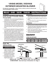
MODEL
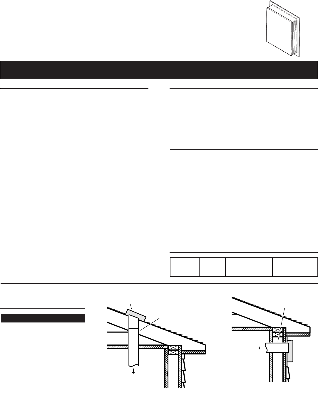
VEDV900
EXTERIOR
BLOWER
10" ROUND DUCT
TO
DOWNDRAFT
WARNING
READ AND SAVE THESE INSTRUCTIONS
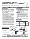
VIKING MODEL VEDV900
EXTERIOR MOUNTED BLOWER
FOR USE WITH VIKING MODEL VIPR101, VIPR161, VIPR181, VIPR101R, VIPR161R AND
VIPR181R DOWNDRAFT VENTILATORS
TO REDUCE THE RISK OF FIRE, ELECTRIC
SHOCK, OR INJURY TO PERSONS, OBSERVE
THE FOLLOWING:
1. Use this unit only in the manner intended by the
manufacturer. If you have questions, contact the
manufacturer or your distributor.
2. Before servicing or cleaning unit, switch power off
at service panel and lock the service disconnect-
ing means to prevent power from being switched
on accidentally. When the service disconnecting
means cannot be locked, securely fasten a promi-
nent warning device, such as a tag, to the service
panel.
3. Installation work and electrical wiring must be done
by a qualified person(s) in accordance with all
applicable codes and standards, including fire-
rated construction codes and standards.
4. Sufficient air is needed for proper combustion and
exhausting of gases through the flue (chimney) of
fuel burning equipment to prevent backdrafting.
Follow the heating equipment manufacturer's guide-
line and safety standards such as those published
by the National Fire Protection Association (NFPA),
and the American Society for Heating, Refrigera-
tion and Air Conditioning Engineers (ASHRAE),
and the local code authorities.
WARNING
CAUTION
1. For general ventilating use only. Do not use to ex-
haust hazardous or explosive material and vapors.
2. To avoid motor bearing damage and noisy and/or
unbalanced impellers, keep drywall spray, con-
struction dust, etc. off power unit.
3. Please read specification label on product for
further information and requirements.
4. Electrical circuit, including speed control, (if used),
must be rated 6 AMPS minimum.
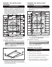
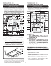
Blower Dimensions
28.25 x 24.75 x 7.17
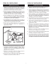
PLAN THE
INSTALLATION
1. Locate the blower so the
length of the duct run and
number of elbows needed
are kept to a minimum.
2. Where possible, blower
should be centered between
wall studs or roof rafters.
3. Avoid pipes, wires, or other
ductwork that may be run-
ning through the wall.
ALL INSTALLATIONS
MODEL VOLTS AMPS CFM DUCT SIZE
VEDV900 120 5.7 900 10 " DIA.
SPECIFICATIONS
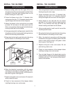
5. When cutting or drilling into wall, or ceiling, do not
damage electrical wiring or other hidden utilities.
6. Ducted fans must always be vented to the out-
doors.
7. To reduce risk of fire, use only metal ductwork.
8. This unit must be grounded.
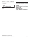
MODEL VEDV900
EXTERIOR BLOWER
10" ROUND
DUCT
TO
DOWNDRAFT
TYPICAL ROOF MOUNTED INSTALLATION
TYPICAL
WALL MOUNTED INSTALLATION
INSTALLER: Leave This Manual With The Homeowner
HOMEOWNER: Use And Care Information On Page 4