


4 USSC
(a)
(a)
(c)
(h)
(f)
(g)
(b)
(e)
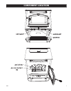
6041I ASSEMBLY
(i)
(j)
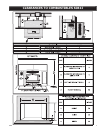
For the following assemblies, we suggest locating the unit
near it’s desired location. Depending on installation, you
may want to connect the exhaust venting before installing
the facade parts.
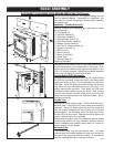
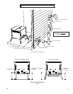
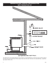
Assembly - Facade (Surround)
Remove contents from packaging and make sure you have
all components:
(2) Top Facade (a)
(1) Left Side Facade (b)
(1) Right Side Facade (c)
(4 pieces)Facade Trim Kit (d)
(1) Feed Door Spring Handle (e)
(1) Damper Spring Handle (f)
(1) Ash Pan “U” shaped Handle (g)
(1) Access Door Knob (h)
(1) PCB Cover (i)
(1) Panel Cover (j)
(1) Auger (in ash pan)
(1) Power Cord
(1) Burnpot Poker (k)
Mounting Hardware
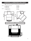
Start by mounting either the left or right side facade pieces to
the unit using four(4) of the supplied #10 x 1/2 screws. Then
put the two(2) top facade pieces together with two(2) of the
#10 x 1/2 screws provided. Attach the top facade assembly
to the unit with eight(8) of the same screws.
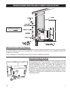
Control Board (PCB) Re-location
Remove the left side front panel from the unit. While holding
the PCB with one hand, remove the two(2) hex head screws
holding the board in place. It is not necessary to unplug the
PCB cable. Route the board and cable through the opening
and mount it to the Left Facade using two of the #10 x 1/2
phillips head screws provided. Then attach the PCB cover
to the back of the facade covering the board. Next, use the
two hex head screws removed earlier and mount the cover
panel over the opening where the PCB was located. See il-
lustration to the left.
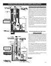
Facade Trim
Remove trim from shipping tube. There should be one(1)
left side, one(1) right side, two(2) top pieces, and mounting
hardware. Using one blank corner key and one corner key
with set screws, assemble the left trim and one of the top
pieces together. As illustrated, place the blank key behind
the key with the set screws. Adjust corners and tighten set
screws. Repeat this for the right side
Before removing tape, place trim assembly against facade
to get an idea of how it is to be mounted. Remove the strip
from the adhesive and carefully secure the trim in place by
rmly pressing it to the facade.
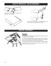
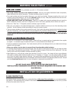
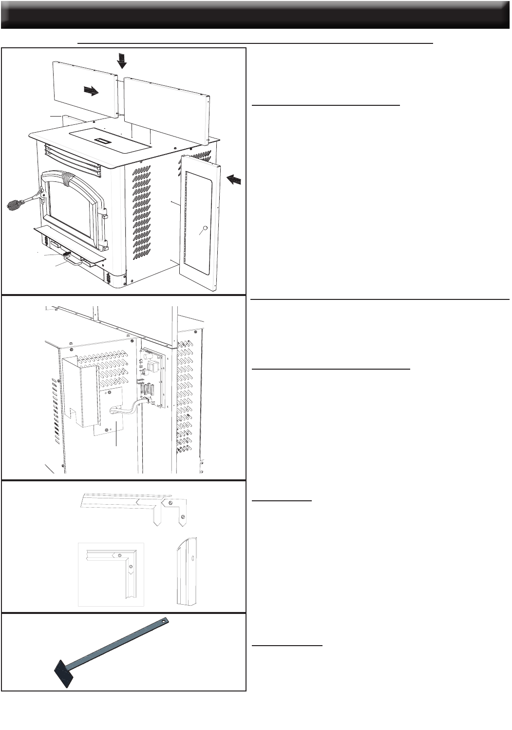
Burnpot Poker
The burnpot poker may be used several ways. It is used
primarily as a fuel-loading assistant to help push the fuel to
the rear of the hopper for maximum fueling. It may also be
used for cleaning of ashes or removal of clinkers.
DISCONNECT THE POWER CORD BEFORE SERVICING THIS Heater
Flat Pattern
SCALE 1 / 3
1
1
2
2
3
3
4
4
A A
B B
TOLERANCES
EXCEPT
AS
NOTED
HOLES
+
.005" -.001"
DECIMAL
.XX = 0.03 XXX = 0.010
ANGULAR
`
2
~
DESCRIPTION
BLANK NUMBER
REFERENCE
SCALE
DWN BY
DATE
SIZE
REV
TITLE NUMBER
UNITED STATES STOVE COMPANY
ESTABLISHED 1869
POKER, BURNPOT
25589
AB
6039i
12 GA. HRS
CEC
4/18/2007
1:2
52182
1
OF
1
SHEET
REVISION HISTORY
REV DESCRIPTION DATE BY
A INITIAL RELEASE 4/18/2007 CEC
60°
3.00
1.80
1.13
(0.105)
1.80
B.P.
15.26
0.38
0.75
15.76
14.92
(k)
(d)