


10 USSC
GUIDELINES FOR EXHAUST VENTING SYSTEMS DESIGN
It is recommended that only an authorized installer install your multi-fuel heater, preferably an NFI certied specialist.
The following installation guidelines must be followed to ensure conformity with both the safety listing of this heater and to local
building codes.
INSTALL VENT AT CLEARANCES SPECIFIED BY THE VENT MANUFACTURER.
• A UL listed 3” or 4” type “PL” pellet vent exhaust system must be used for installation and attached to the pipe connector provided
on the back of the heater. Use a 3” to 4” adapter for 4” pipe. A cap must be used at the termination of type “L” vent chimneys.
4” PL is required for elevations above 2,500 feet above sea level.
• Do not terminate vent in any enclosed or semi-enclosed area, such as; carports, garage, attic, crawl space, under a sundeck or porch,
narrow walkway or close area, or any location that can build up a concentration of fumes such as a stairwell, covered breezeway
etc.
• Vent surfaces can get hot enough to cause burns if touched by children. Noncombustible shielding or guards may be required.
• Do not install a ue damper in the exhaust vent of this unit.
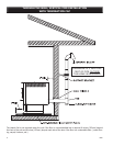
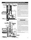
• Termination must exhaust above air inlet elevation. Installation MUST include three (3) vertical feet of pellet vent pipe. This will
create some natural draft to prevent the possibility of smoke or odor during appliance shutdown and to keep exhaust from caus-
ing a nuisance or hazard from exposing people or shrubs to high temperatures. Do not connect this unit to a chimney ue
serving another appliance. Do not connect directly to a masonry chimney.
• The installation must include a cleanout tee to enable collection of y ash and to permit periodic cleaning of the exhaust system.
90
°
elbows accumulate y ash and soot thereby reducing exhaust ow and performance of the heater. Each elbow or tee reduces
draft potential by 30% to 50%. Use no more than 180 degrees of elbows (two 90-degree elbows, or two 45-degree and one
90-degree elbow, etc.) and one cleanout tee to maintain adequate draft. Cleanout tees and elbows should not be connected to
the rear of the unit unless a 3-inch adapter is used.
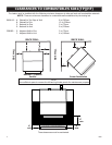
• Total length of horizontal vent must not exceed 48”(4ft.)/1,200mm. The maximum recommended vertical venting height is 12-feet
for 3-inch type “PL” vent. For venting higher than 12-feet, 4-inch “PL” vent must be used. All joints in the vent system must be
fastened by at least 3 screws, and all joints must be sealed with RTV silicone sealer to be airtight.
• The area where the vent pipe penetrates to the exterior of the home must be sealed with silicone or other means to maintain the
vapor barrier between the exterior and the interior of the home.
NOTE: These are guidelines only. Proper venting is accomplished by design and necessary requirements. In
most installations 3 inch diameter venting is adequate. If it does not vent properly you will have to change it to 4
inches. You should not exceed 4 inch diameter venting.
DO NOT CONNECT TO ANY AIR DISTRIBUTION DUCT OR SYSTEM
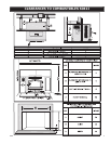
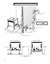
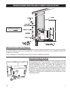
VENT TERMINATION CLEARANCES:
A) Min. 4-ft clearance below or beside any door or window that opens.
B) Min. 1-ft clearance above any door or window that opens.
C) Min. 3-ft clearance from any adjacent building.
D) Min. 7-ft clearance from any grade when adjacent to public walkways.
E) Min. 2-ft clearance above any grass, plants, or other combustible materials.
F) Min. 3-ft clearance from a forced air intake of any appliance.
G) Min. 2-ft clearance below eaves or overhang.
H) Min. 1-ft clearance horizontally from combustible wall.
I) Must be a minimum of 36-inches above the roof and 24-inches above the highest point or the roof within 10-feet.