24
Auger Drive Belt Adjustment
Due to wear, the auger drive belt may
begin to slip when the auger drive lever is
engaged. To adjust the auger drive belt:
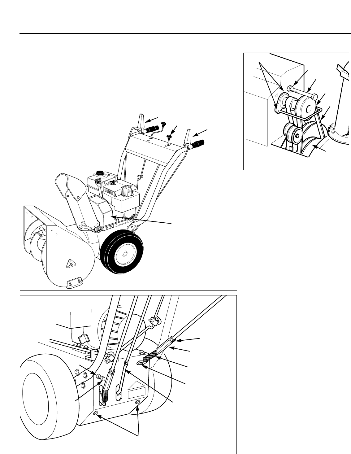
1. Perform the brake arm adjustment as
described later in this section.
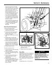
2. If assembling a new unit, raise the
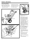
wheel drive control lever (AP, Fig. 5-9)
and the auger drive control lever (AL).
3. Pull the auger drive control arm (AJ,
Fig. 5-10) down completely.
4. Measure and note the length of the
spring (AK, Fig. 5-10).
5. Squeeze the auger drive control lever
(AL, Fig. 5-9) against the handlebar.
Measure the length of the spring (AK,
Fig. 5-10) again. The spring length
should now measure 9/16" – 11/16".
(14–17mm) longer than the
measurement taken in step 4. If it does
not, loosen the jam nut (AM) and turn
the adjuster (AN) to increase or
decrease the length of the spring. Hold
the adjuster and tighten the jam nut
(AM) when the correct spring length is
obtained. Re-check the measurements
and adjust if needed.
NOTE: 1-1/4 turns of the adjuster equals
1/16" (1.5mm) of spring extension.
Auger Drive Belt Replacement
To remove the auger drive belt:
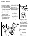
1. Remove the bolts, flat washers, and
lockwashers securing the belt cover
(AB, Fig. 5-9) to the unit. Remove the
belt cover.
2. Remove the two bolts securing the
belt guide (AC, Fig. 5-11) to the
engine. Remove the belt guide.
3. Loosen jam nut (BC) and remove bolt
(BD).
4. Remove the auger drive belt (AD) from
the auger drive pulley (AE).
Section 5: Maintenance
Fig. 5-9
AB
AL
Fig. 5-11
AC
AD
BD
BC
AE
AO
Fig. 5-10
Q
AK
AJ
AA
AN
AM
AX
AW
AU
AP


