


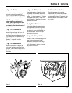

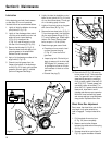
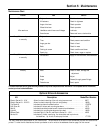
length of spring (W, Fig. 5-6) again.
The spring length should now measure
5/8" – 3/4" (15–19mm) longer than the
measurement taken in step 2. If it
does not, loosen jam nut (Y, Fig. 5-6)
and turn adjuster (Z, Fig. 5-6) to
increase or decrease the spring length.
(1-1/4 turns of the adjuster equals
1/16" [1.5mm] of spring extension.)
Hold the adjuster and tighten the jam
nut (Y) when the correct spring length
is obtained. Re-check measurements
and adjust if needed.
If after completing this adjustment the
wheels do not drive adequately, refer
to “Drive Disc Clearance Adjustment”
on page 25. Then repeat this
adjustment.
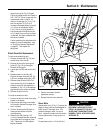
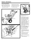
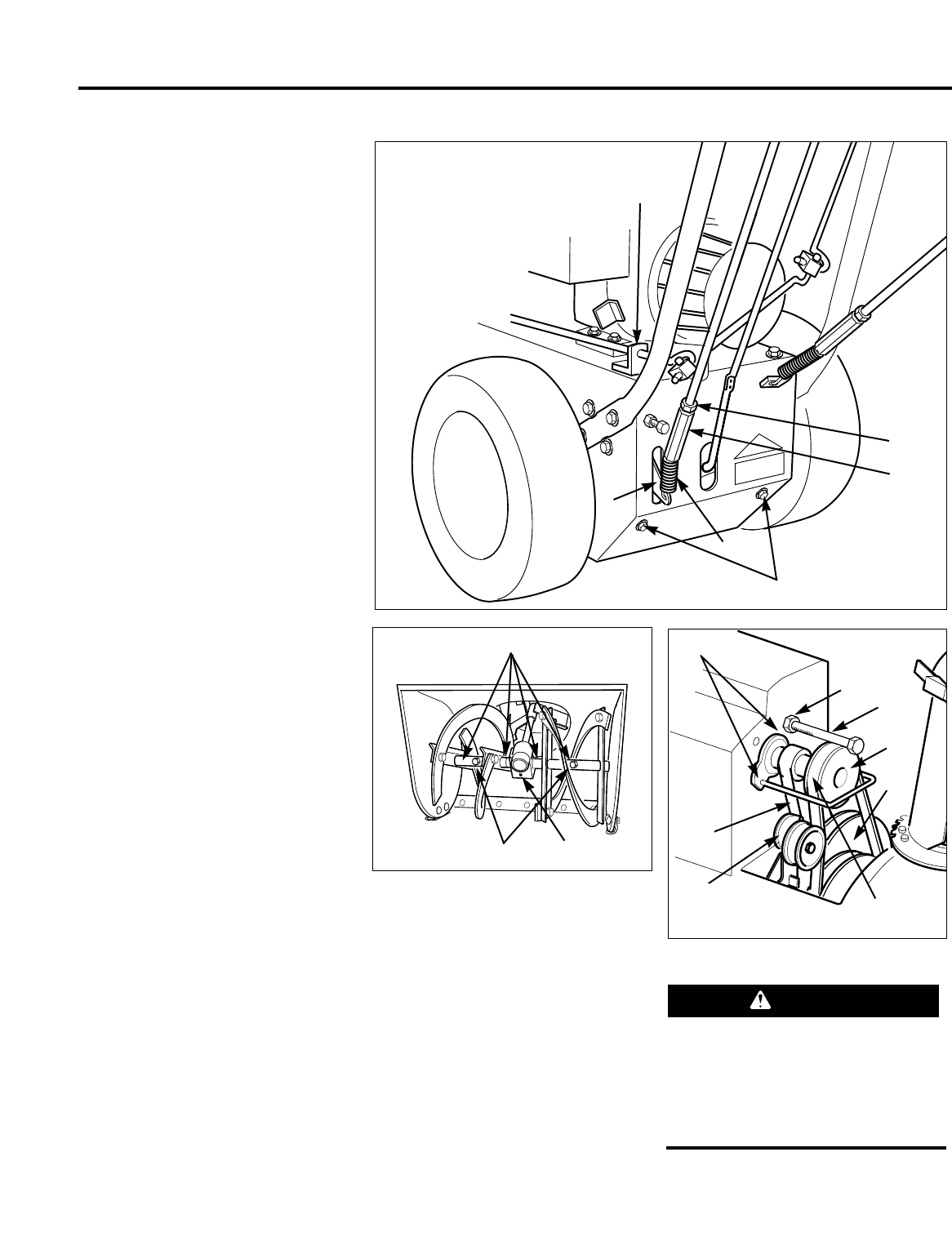
Wheel Drive Belt Replacement
To remove the wheel drive belt:
1. Remove the bolts (AB, Fig. 5-3) and
the belt cover from the unit.
2. Remove the two bolts securing belt
guide (AC, Fig. 5-8) to the engine.
Remove the belt guide.
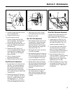
3. Loosen jam nut (BA) and remove bolt
(BB).
4. Release tension on the idler (AF).
Remove the auger drive belt (AD, Fig.
5-8) from the auger drive pulley (AE).
5. Remove wheel drive belt (AG) from
lower drive pulley (AH). Squeeze the
wheel drive control lever against the
handlebar (X, Fig. 5-3) to increase the
gap between lower pulleys as needed.
6. Remove the belt from unit.
To install the wheel drive belt:
1. Position the belt into lower drive pulley
closest to the engine.
2. Place the belt into the groove closest
to the engine. Reinstall the auger drive
belt in its pulley.
3. Position the belt guide (AC) back on
the engine and secure with bolts
removed earlier.
4. Reinstall bolt (BB), leaving 1/16"
(1.5mm) clearance between underside
of bolt head and front edge of pulley
(AE). Tighten jam nut (BA) against
engine crankcase.
5. Perform the wheel drive disc
adjustment (above).
6. Reinstall the belt cover and bolts.
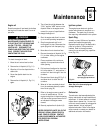
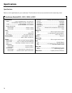
Shear Bolts
Special shear bolts (C, Fig. 5-7) secure the
augers to auger shaft and are designed to
break (shear) if the auger jams. This
prevents damage to other, more vital
parts. Inspect the shear bolts before each
use and replace them if they are worn or
broken.
Torque shear bolts to 11 ft-lbs (15 Nm).
Section 5: Maintenance
Fig. 5-6
V
Q
W
G
Fig. 5-7
Fig. 5-8
C
AC
Y
Z
AD
BB
BA
AE
AH
AG
AF
P
O
CAUTION
USING ANYTHING BUT ORIGINAL
EQUIPMENT SHEAR BOLTS COULD
RESULT IN DAMAGE TO THE UNIT. USE
AUGER SHAFT SHEAR BOLTS PART
NUMBER 1735625, WHEN REPLACING
SHEAR BOLTS.
23