


14
Controls
This section defines the various controls
on the unit. Refer to the following section,
“Operation,” for an explanation of the
proper use of these controls.
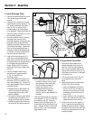
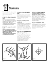
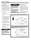
A, Fig. 3-1—Wheel drive control
lever
Controls the engagement of the wheel
drive. When this lever is down against the
handlebar and the engine is running, the
wheels will rotate. Refer to the
“Maintenance” section of this manual for
the proper adjustment information.
B, Fig. 3-1—Auger drive control
lever
Controls the engagement of the auger
drive. When this lever is down against the
handlebar and the engine is running, the
auger will rotate. Refer to the
“Maintenance” section of this manual for
the proper adjustment information.
C, Fig. 3-1—Gear shift control
lever
Controls the selection of travel speeds:
five forward and two reverse positions.
Refer to the “Maintenance” section of this
manual for the proper adjustment
information.
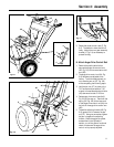
D, Fig. 3-1—Discharge chute
control rod
Controls the direction the discharge chute
is facing. Rotate this crank clockwise to
turn the discharge to the right; rotate
counter-clockwise to turn the discharge
chute to the left. Approximately ten turns
of this crank will move the discharge chute
all the way from one side to the other.
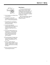
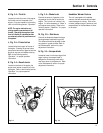
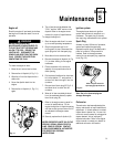
E & F, Fig. 3-2—Discharge chute
deflector cap and lever
Controls the vertical angle of the snow
discharge. To adjust the discharge angle:
move the discharge cap by pulling lever
(F, Fig. 3-2) outward and moving the
discharge deflector cap up or down. The
discharge chute deflector cap should
usually be adjusted to a low angle,
especially in windy conditions.
G, Fig. 3-1—Ignition keyswitch
The keyswitch has two positions: “
”
RUN and STOP. Rotating the key to the
“
”
RUN position allows the engine to be
started. Rotating the key to the STOP
position stops the engine. Always remove
the ignition key when the unit is not in
use. Store the key in a safe place out of
the reach of children.
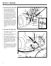
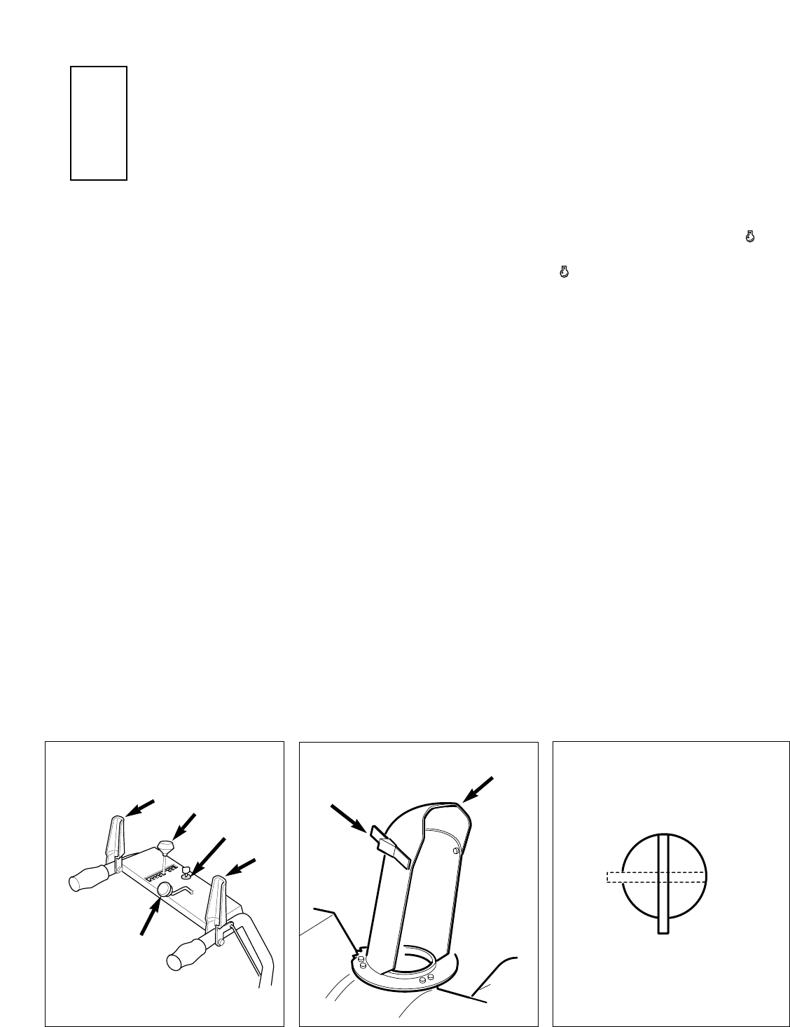
Fig. 3-3—Fuel shut-off valve
Located beneath the fuel tank, the fuel shut-
off valve (Fig. 3-3) controls fuel flow from
the fuel tank to the carburetor. Refer to the
engine owner manual for complete
information.
Fig. 3-1
Fig. 3-2
ON
OFF
Fig. 3-3
C
F
E
D
B
A
G
Section
3