


11
Section 2: Assembly
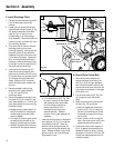
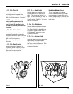
Fig. 2-7
Y
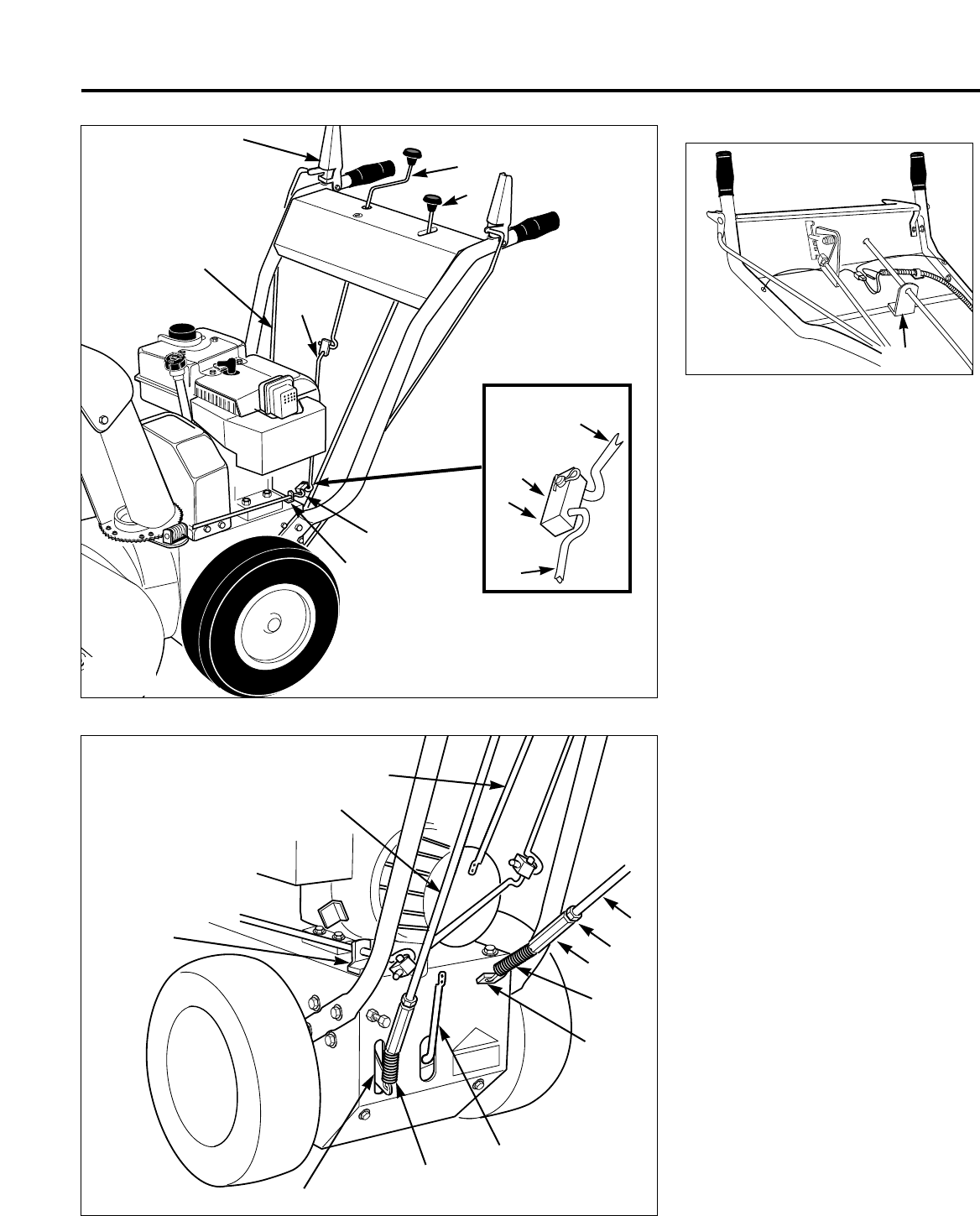
Fig. 2-8
AH
AC
AD
AB
AA
AT
AS
AG
R
AF
AE
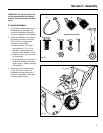
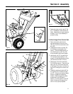
5. Rotate the chute control crank (Z, Fig.
2-6). The deflector chute should turn
freely. Adjust the worm gear assembly
bracket (L, Fig. 2-4) as necessary to
prevent binding.
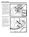
H. Attach Auger Drive Control Rod
1. Remove the plastic cable tie that
secures the auger drive control arm
(AD, Fig. 2-8) to the transmission shift
arm (AB).
2. The auger drive control rod (AA, Fig.
2-8) has been pre-adjusted at the
factory. To avoid misadjustment, do
not rotate the jam nut (AT, Fig. 2-8)
while completing the following steps.
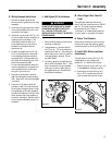
3. Hold the jam nut (AT) in place with a
7/16" wrench and use another 7/16"
wrench to thread the adjusting thimble
(AS) downward a total of 12 turns.
4. Raise auger drive control handle (X,
Fig. 2-6) all the way up. Then hook the
spring (AC, Fig. 2-8) at the lower end
of the auger drive control rod (AA) into
the hole in the auger drive control arm
(AD).
5. Thread the adjusting thimble (AS, Fig.
2-8) upward until it contacts the jam
nut (AT). Using two wrenches, tighten
the jam nut against the adjusting
thimble. When the engine is started,
as described in the “Operation”
section, you will be given a functional
check to make sure the auger drive
control rod is properly adjusted.
Fig. 2-6
Z
T
R
U
U
V
W
S
S
AA
X