


10
Section 2: Assembly
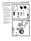
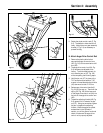
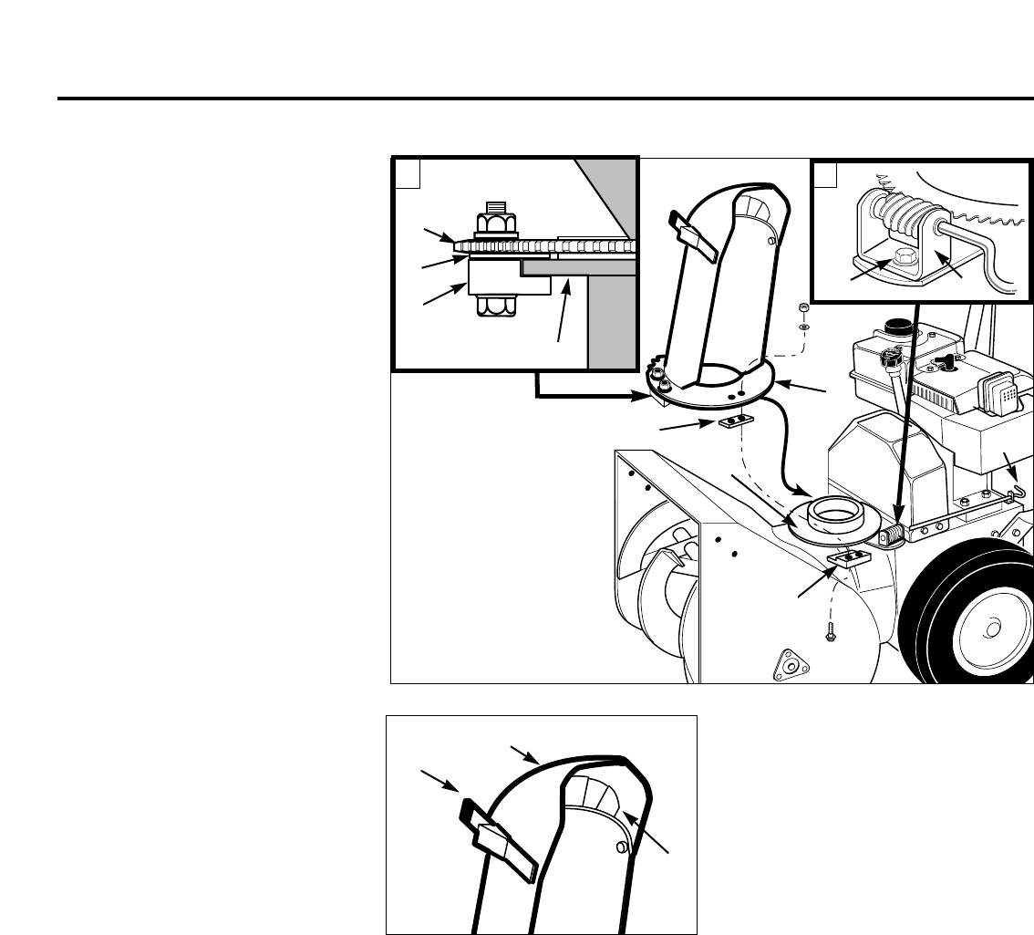
F. Install Discharge Chute
1. Remove the cardboard packing shield
from the discharge chute mount
opening.
2. Loosen (do not remove) the left and
right side sets of plastic shims (G, Fig.
2-4, inset A) and plastic hold-down
clips (H, Fig. 2-4, inset A) on the
toothed flange (J) of the discharge
chute assembly. Remove and save the
remaining (front) hold-down clip, shim
and mounting hardware.
3. From either side of the unit, slide the
discharge chute onto the chute
mounting flange (K), making sure that
the plastic shims (G) are above the
flange and the plastic hold-down clips
(H) are below the flange. Tighten the
shim mounting hardware securely (if
necessary, rotate the discharge chute
to the right in order to tighten the left
side shim and hold-down clip).
4. Hook the front hold-down clip (H)
under the mounting flange (K) and
place the front plastic shim (G) on top
of the hold-down clip, between the top
of the flange and the toothed chute
flange. Using two 5/16" wrenches,
secure with the screws, washers and
locknuts.
5. Remove the plastic cable tie that
secures the worm gear assembly
(L, Fig. 2-4 inset B) to the
mounting bracket.
6. Remove the washer and locknut from
the screw (M, Fig. 2-4 inset B) in the
worm gear assembly (L). Position the
worm gear assembly on the mounting
bracket as follows:
a. Engage the worm gear threads 1/2-
way with the teeth on the flange of
the discharge chute base (rotate
chute as needed).
b. The length of the worm gear should
be centered with the teeth on the
flange of the discharge chute base.
c. Reinstall the washer and locknut on
the screw (M) and tighten securely.
Fig. 2-4
d. Turn chute control rod (F, Fig. 2-4)
by hand to be sure the worm gear
and discharge chute rotate freely,
but with enough resistance to
prevent free rotation of the
discharge chute during snow
removal operation. Readjust
position of worm gear assembly as
necessary.
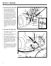
7. Insert the flexible fingers on the plastic
snow deflector (N, Fig. 2-5) inside the
chute deflector cap (O). Close the
deflector cap by pulling the lever (P)
outward and moving the deflector cap
down. Release the lever to secure the
deflector cap in one of the discharge
angle selector holes.
G. Attach Chute Control Rod
1. Remove the plastic cable tie that
secures the auger drive control rod
(AA, Fig. 2-6) to the right handlebar.
Next, remove the plastic cable tie that
secures the chute crank rod (short rod
with plastic swivel blocks) to the auger
drive control rod.
2. Pull the chute crank rod (Z, Fig. 2-6)
up through the top of the control
panel.
3. Attach the chute control rod sections
(S and U, Fig. 2-6) as follows:
a. Insert the angled end of the chute
control rod, (U, Fig. 2-6 inset) into
the hole in the swivel block (V) that
is attached to the end of the chute
crank rod (S).
b. Insert a cotter pin (W) through the
hole in the chute control rod (U) and
spread the ends of the cotter pin.
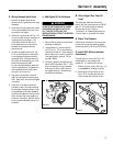
4. Position the chute control support (Y,
Fig. 2-7) against the underside of the
handlebar console as shown. Secure
the support with the two #10–24 x 3/8"
Phillips pan head screws and #10–24
locknuts supplied.
Fig. 2-5
N
P
O
A
B
H
K
L
M
(Front shim) G
(Front hold-
down clip) H
J
F
K
J
G