


14
5
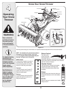
Making
Adjustments
WARNING
Read, understand, and
follow all instructions
and warnings on the
machine and in this
manual before operat-
ing.
Never attempt to
make any adjustments
while the engine is
running, except where
specified in operator’s
manual.
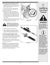
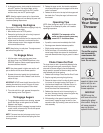
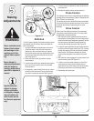
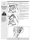
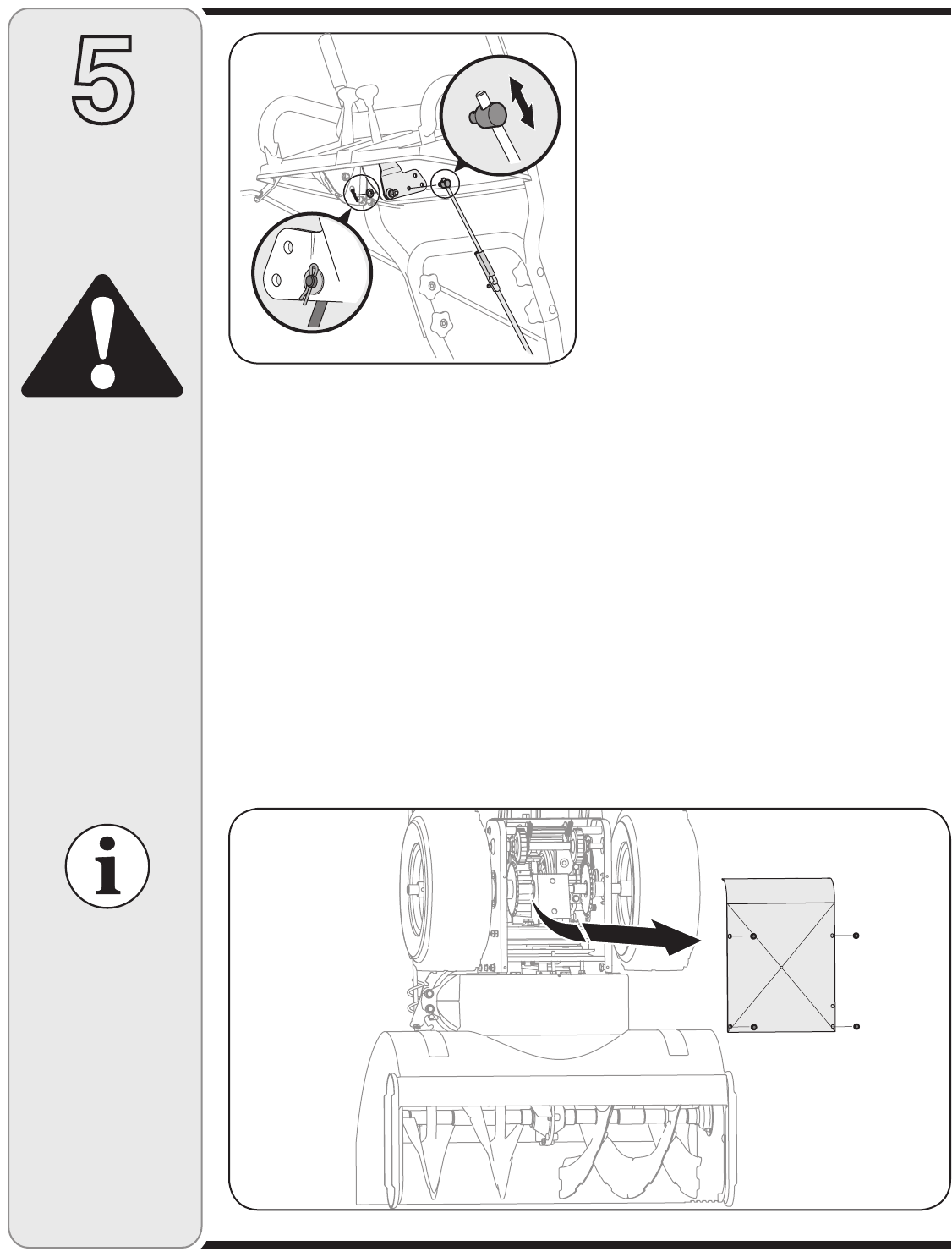
Shift Rod
If the full range of speeds (forward and reverse) cannot
be achieved, refer to the figure above and adjust the
shift rod as follows:
1. Looking underneath the handle panel, note which
of the three holes in the shift lever the ferrule is
inserted into. Also note the direction of insertion.
Remove the internal cotter pin and flat washer from
the ferrule and withdraw the ferrule from the shift
lever. See Figure 5-1.
2. Place shift lever in sixth (6) position or fastest
forward speed.
3. Push shift rod and shift arm assembly down sharply
as far as it will go to put the drive into the fastest
forward position.
4. As necessary, rotate (thread) the ferrule up or down
the shift rod until the ferrule lines up with the hole
from which it was earlier removed. See Figure 5-1.
5. From the direction noted earlier, insert the ferrule into
the proper hole.
6. Reinstall the washer and the internal cotter pin.
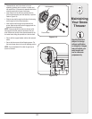
Chute Control
The distance snow is thrown can be adjusted by adjusting
the angle of the chute assembly. Refer to “Operating Your
Snow Thrower” for instructions.
The remote chute control cables have been pre-adjusted
at the factory. Move the remote chute lever on the control
panel back and forward to adjust angle of the chute
assembly.
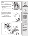
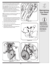
Drive Control
Refer to the Final Adjustment section of the Assembly
instructions to adjust the drive control. To further check
the adjustment, proceed as follows:
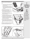
1. With the snow thrower tipped forward (be certain to
drain gasoline or place plastic film under the gas cap if
the snow thrower has already been operated), remove
the frame cover underneath the snow thrower by
removing the self-tapping screws. See Figure 5-2.
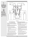
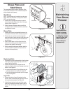
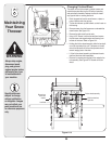
2. Locate the opening between the axle support bracket
and the front frame support (See Figure 5-3). Looking
through this opening, with the drive control released,
there must be 1/8” clearance between the friction
wheel and the drive plate in all positions of the shift
lever.
3. With the drive control engaged, the friction wheel must
contact the drive plate. See Figure 5-3.
4. If there is no friction wheel clearance, or the friction
wheel does not solidly contact the drive plate, re-
adjust the lock nut on the lower end of the drive cable
following the instructions in the Assembly section.
5. Reassemble the frame cover.
Figure 5-1
Figure 5-2
Specifications are
subject to change
without notification
or obligation. Images
may not reflect your
exact model and are
for reference purposes
only.