


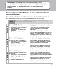
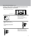
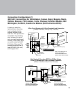
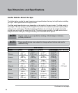


24
Pigtail
Neutral Bus
Ground
TB2
TB1
Black (L)
White (N)
Green
Main
Service
Panel
with
GFCI
1-Pole
GFCI
Breaker
Ground/Bonding Lug**
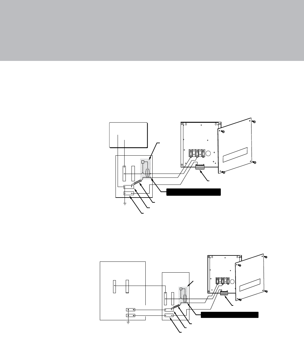
1-Pole Circuit Breaker with 3-Wire Grounded Load Connection
(3 Wires to Hot Tub, 1-Hot (L), 1-Neutral (N), 1-Ground)
White (N)
Black (L)
120 VAC
Load Neutral Lug on Breaker
Note: service disconnect not
shown in this diagram.
The control box TB1 terminal
position varies between models.
BW
Hot Tub
Control Box
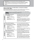
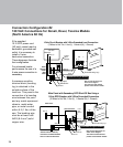
Black (L)
Black (L)
Pigtail
Neutral Bus
Ground
TB2
Green
GFCI Sub Panel*
Main Panel*
1-Pole
GFCI
Breaker
Ground/Bonding Lug**
Load Neutral Lug on Breaker
Main Panel with Secondary GFCI Shut-Off Box Using a
1-Pole GFCI Breaker with 3-Wire Grounded Connection
(3 Wires to Hot Tub, 1-Hot (L), 1-Neutral (N), 1-Ground)
White (N)
Green (Ground)
*GFCI Sub Panel commonly
used when recommended GFCI
does not install in Main Panel.
Note: service disconnect not
shown in this diagram.
The control box TB1 terminal
position varies between models.
Hot Tub
Control Box
White (N)
TB1
BW
Connection Configuration #2
120 VAC Connections for Denali, Dover, Tacoma Models
(North America 60 Hz)
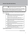
If the supplied
10 ft GFCI power cord
(US only) cannot reach a
dedicated, grounded wall
outlet, it is necessary to
install a 3-wire,
hard-wired connection.
These diagrams illustrate
that conguration.
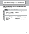
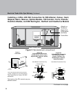
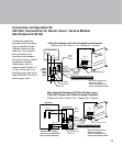
For enhanced heater
performance the use of a
4-wire power connection is
necessary.
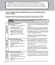
A pressure sensitive
terminal block (bonding
lug) is attached to the
outside surface of the
load box. This permits the
connection of a bonding
wire between this point
and any metal equipment
chassis, metal water
pipe, or metal conduit
within 5 ft (1.5m) of the
spa. The bonding wire
must be at least a #8
AWG (8.4 mm
²) solid
copper wire.