


7600030 RIGHT FENDER SUPPRORT BRACKET KIT FOR
SNAPPER / SIMPLICITY RZT ZERO-TURN RIDING MOWERS
WARNING
DO NOT attempt any adjustments, maintenance, repairs, or service with engine running. Stop engine. Engage
parking brake. Remove key. Remove spark plug wire and secure wire away from spark plug. Engine, muffler and
surrounding areas are extremely hot. Avoid serious burns; allow components to cool down before installing kit.
Replace worn or damaged parts prior to operating. Use approved fuel container. DO NOT smoke near open fuel
container. DO NOT fill fuel tank indoors or when engine is running. Allow engine to cool for at least ten minutes
before refilling. Make sure that fuel cap is tightened securely. Wipe off any spilled fuel before starting engine.
! !
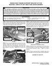
STEP 1: Remove the three torx screws securing the control
panel to the top of the right fender. Lifting the control panel
slightly, remove the two inside clip nuts from the fender used
to secure the two inside torx screws. See Figure 1.
STEP 2: From under the right fender toward the front of the
machine, remove the 1/4-20 nylon lock nut from the bolt
securing the back end of the dampener. Also remove the
3/8-16 nylon lock nut from the bolt securing the twin stick
pivot weldment. See Figure 2. NOTE: Do not remove the
bolts.
STEP 3: Install the fender support bracket onto the bolts,
securing with the 1/4-20 and 3/8-16 center lock nuts in place
of the nylon lock nuts removed in Step 2. Tighten both nuts
securely. Also secure the wiring harness to the noted hole
with the supplied wire tie, to keep the harness from
contacting the drive control rod. See Figure 3.
STEP 4: Aligning the two inside holes in the control panel
with the two holes in the top of the fender bracket, reinstall
the torx screws removed in Step 1. Tighten the screws
securely.
STEP 5: Check to make sure that all assembly steps have
been completed and that all hardware is securely tightened.
ASSEMBLY IS COMPLETE
FIGURE 1
FIGURE 3
INSTRUCTION No. 7100662 (I.R. 3/2/2006)
TP 200-5167-IR-AT-SN
FENDER
SUPPORT
BRACKET
REMOVE THE CLIP
NUTS SECURING
THESE TWO SCREWS
KIT CONTENTS:
7300354 - RH FENDER SUPPORT BRACKET (1 QTY) 0-92126 - 1/4-20 CENTER LOCK NUT (1 QTY)
0-91585 - 3/8-16 CENTER LOCK NUT (1 QTY) 0-12080 - WIRE TIE (1 QTY)
(Right fender removed for clarity)
FIGURE 2
REMOVE THESE TWO
NYLON LOCK NUTS
SECURE WITH SUPPLIED
CENTER LOCK NUTS
REMOVE THESE
THREE SCREWS AND
LIFT CONTROL PANEL
SECURE WIRING
HARNESS TO
THIS HOLE WITH
WIRE TIE