


1
SET-UP INSTRUCTIONS & PRE-OPERATION CHECKLIST
For SNAPPER “W” SERIES REAR ENGINE RIDERS
INTRODUCTION: The SNAPPER “W” Series Rear Engine Riders are shipped fully assembled and require
minimal set-up. Complete each of the following steps carefully. Review and complete each item as instructed
on the Pre-Operation checklist. The Snapper Product Registration card must be filled out and sent to Customer
Service department at Snapper when completed.
BATTERY ACTIVATION and INSTALLATION
Snapper riders with a model prefix “W” are supplied with
wet batteries and do not require the addition of
electrolyte. All batteries require a slow charge before
being placed into service.
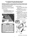
1. BATTERY REMOVAL
A. Remove battery cover by pulling each side away
from ratchet fasteners. See Figure 1.
B. Remove the hair pin and swivel from the deck
support to allow clearance for battery removal.
C. Remove battery from battery compartment.
FIGURE 1
WARNING
The electrolyte (acid) produces a highly explosive gas.
Keep all sparks, flame and fire away from area when
charging battery or when handling electrolyte or
battery. Electrolyte (acid) is a highly corrosive liquid.
Wear eye protection. Wash affected areas immediately
after having eye or skin contact with electrolyte (acid).
Battery acid is corrosive. Rinse empty acid containers
with water and mutilate before discarding. If acid is
spilled on battery, bench, or clothing, etc., Flush with
clear water and neutralize with baking soda. DO NOT
attempt to charge battery while installed on the RIDER.
DO NOT use “BOOST” chargers on the battery. DO
NOT OVER FILL!
2. BATTERY CHARGING
A. With all cell caps removed, connect an
automotive type battery charger to battery
terminals; RED to positive (+) and BLACK to
negative (-) terminal.
B. Slow charge at 2 to 6 amps for 30 minutes.
C. After charging, check level of electrolyte, add
water only if necessary, and tighten cell caps.
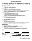
3. BATTERY INSTALLATION
A. Slide battery partially into box, with positive end to
inside and terminals to rear, to allow for cable
installations.
B. Battery cables MUST BE SECURED TO
BATTERY TERMINALS as shown in Figure 2,
using the 1/4” screws, that are mounted on
terminals, and lock nuts from the hardware bag.
C. Install positive (+) cable first. Place the positive
(+) terminal insulator over positive terminal and
cable. Install negative (-) cable last after
positive
terminal insulator has been installed.
See Figure 2.
D. Slide battery into battery box and reinstall battery
cover.
E. Reinstall deck support swivel and hair pin.
FIGURE 2
INSTRUCTION No. 7-5122 (I.R. 6/28/02)
POSITIVE
TERMINAL
INSULATOR
CABLES MUST
BE MOUNTED
TO TERMINALS
AS SHOWN
RED POSITIVE (+)
CABLE
BLACK
NEGATIVE (-)
CABLE
TO OUTSIDE OF
MOWER
PULL COVER AWAY
FROM RATCHET
FASTENERS ON
BOTH SIDES