


ELECTRIC START SYSTEM DEALER SET-UP INSTRUCTIONS for
SNAPPER LARGE FRAME SNOW THROWERS
INTRODUCTION: It will be necessary to complete Dealer Set-Up Instruction #2-8224 first before attempting to
install the electrical components described in this Electric Start System Dealer Set-Up Instruction.
WARNING: Always disconnect spark plug wire from spark plug before performing maintenance on snow
thrower. DO NOT operate snow thrower without guards in place. DO NOT put hands into areas that house
rotating parts while machine is in operation!
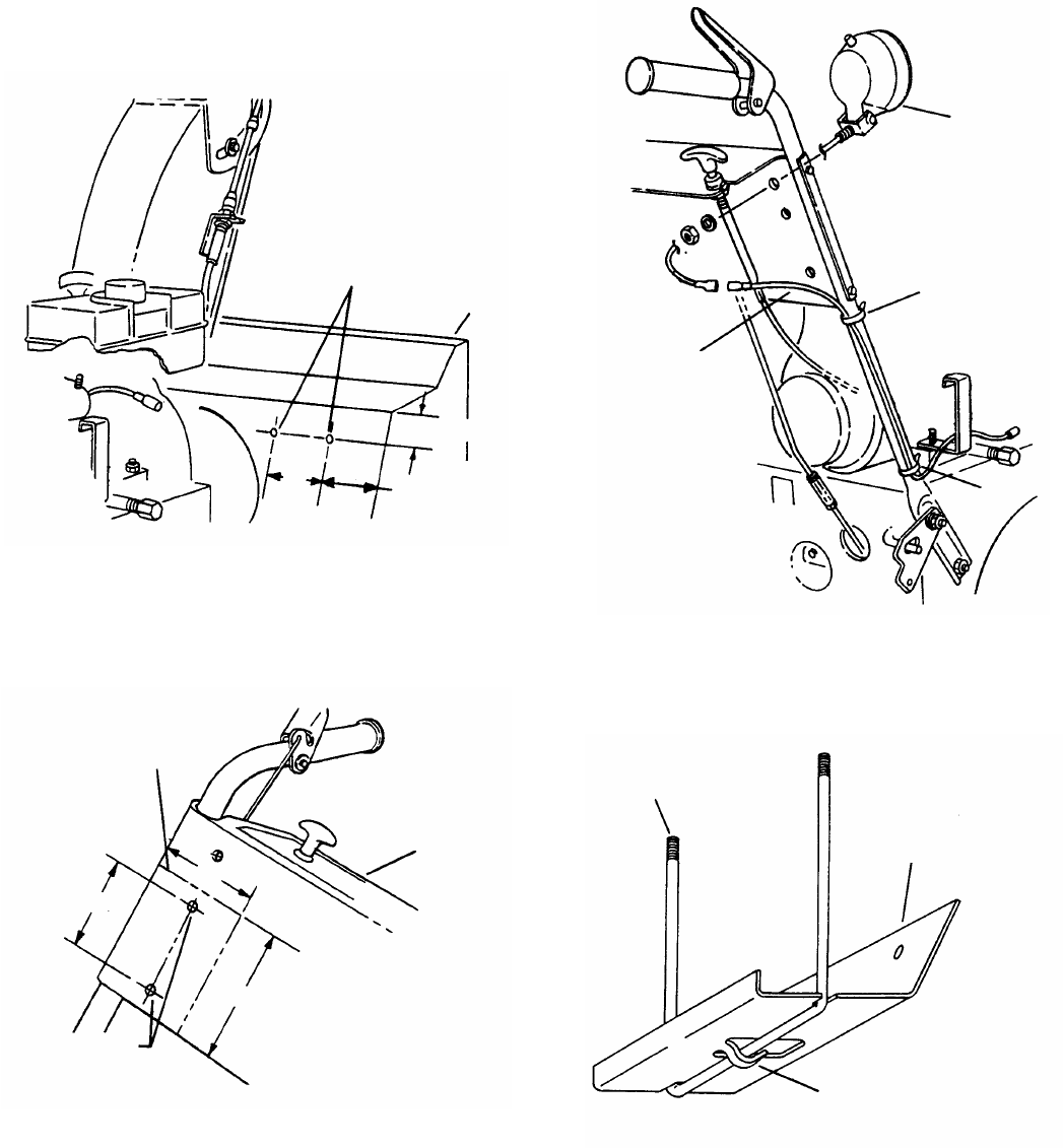
STEP 1: Drill two 5/16 diameter holes in right side of
auger housing using dimensions shown. See Figure 1.
FIGURE 1
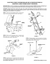
STEP 2: Drill two 5/16 diameter holes in control panel
within the 5” by 7” boundary lines shown. Drill holes
using dimensions shown. See Figure 2.
FIGURE 2
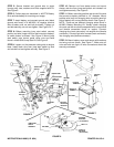
STEP 3: Install light onto control panel with washer and
nut and tighten securely. Install light wire harness into
end of light wire and route down handle and secure with
ties as shown. See Figure 3.
FIGURE 3
STEP 4: Remove battery mounting bracket and battery
clamp from #6-0651 Battery Mounting Kit and assemble
these parts as shown. See Figure 4.
FIGURE 4
INSTRUCTION #2-9693 (I.R. 8/94)
5/16 DIAMETER
HOLES
AUGER
HOUSING
3-7/16”
4”
4-5/16”
BOUNDARY
LINES
CONTROL
PANEL
5”
5-3/4”
7”
5/16 DIAMETER
HOLES
LIGHT
TIE
LIGHT WIRE
HARNESS
TIE
BATTERY MOUNTING
BRACKET
BATTERY CLAMP
BEND TAB OVER