


Start the Engine
• Sit in the seat.
• Engage the parking brake: Press the brake pedal (Figure
7) down, and pull the parking brake lever (A, Figure 8) up.
• Push the PTO (blade engage) switch (B, Figure 8) to
OFF (‘O’).
• Move the throttle control (A, Figure 9) to FAST.
• Move the choke control (B, Figure 9) to CHOKE.
• Turn the ignition key (C, Figure 8) to START.
• After the engine starts, release the ignition key,
and move the choke control to OFF.
Note: Always set the throttle control to FAST when driving and mowing.
Drive the Unit Off the Crate
• Move the deck lift lever (Figure 12) to the highest cutting height.
• Disengage the parking brake: Press and release the brake pedal.
• Slowly press the speed control pedal (Figure 10) forward to drive the unit
off the crate.
• If the unit does not move, set the automatic drive disconnect (Figure 11),
located behind the unit next to the right rear wheel, to DRIVE.
Mowing
• Read the Operator’s Manual before mowing.
• Move the deck lift lever (Figure 12) to the desired cutting height.
• Pull the PTO (blade engage) switch (Figure 13) to ON (‘I’).
• Begin mowing.
WARNING: Do not use the Reverse Mowing Option (RMO) feature until you
have carefully read the Reverse Mowing Option Section of the Operator’s
Manual.
Stopping the Tractor, Blades, and Engine
• Slowly release the speed control pedal.
• Push the PTO (blade engage) switch down to OFF (‘O’).
• Engage the parking brake: Press the brake pedal, and pull the parking brake lever up.
• Move the throttle control to SLOW.
• Turn the ignition key to OFF (‘O’). Remove the key.
Unpack the Unit
• Remove all packaging materials from the crate and the unit. Remove any banding securing the unit to the crate.
• Locate and identify the items included with the unit.
Read the Manuals
• Carefully read all the manuals supplied with the unit. They contain important safety, operating, and maintenance information.
Install the Seat
• Insert the two posts under the seat (A, Figure 1) into the rear adjustment slots in the hinge
plate (B).
• Install the two wing bolts and small washers (C) through the front adjustment slots in the
hinge plate and into the threaded holes under the seat.
• Adjust the seat as desired, then tighten the wing bolts.
Install the Steering Wheel
• Turn the front wheels of the tractor straight ahead.
• Install the steering shaft bellows (Figure 2) over the steering shaft.
• Install the steering wheel (Figure 3) onto the steering shaft, making sure the
steering wheel is aligned straight.
• Fasten the steering wheel to the steering shaft with the hex bolt and large
washer. Tighten securely.
• Attach the steering wheel cover (Figure 4) to the center of the steering wheel.
Connect the Battery
• Raise the seat.
• Check the date on the top or side of the battery. If the unit is being put into service after the
date indicated on the battery, charge the battery for one hour at 6-10 amps.
• Install the terminal cover (not shown) onto the red cable.
• Connect the red cable to the positive (+) battery terminal (A, Figure 5) with a carriage bolt
and wing nut. Tighten securely. Slide the terminal cover over the connection.
• Connect the black cable to the negative (-) battery terminal (B, Figure 5) with a carriage bolt
and wing nut. Tighten securely.
• Lower the seat.
Check the Tire Pressure
• Adjust the pressure of the front and rear tires to 14 PSI.
Note: The tires may be overinflated for shipping purposes.
Check the Engine Oil Level
Note: The engine is shipped with oil. However, the oil level should be checked before
attempting to start the engine.
• Move the tractor to a flat, level surface.
• Raise the tractor hood to access the engine compartment.
• Remove the oil fill cap (A, Figure 6). Wipe the dipstick, replace the cap, then remove and
check the oil level. The oil level should be between the ‘Full’ and ‘Add’ marks on the dipstick.
• If necessary, add premium 10W-30 oil to the engine. Recheck the oil level.
• Replace and secure the oil fill cap.
Add Fuel
• Remove the fuel cap (B, Figure 6).
• Add clean, fresh, unleaded fuel with a minimum of 87 octane to the fuel tank.
• Replace the fuel cap, and wipe up any fuel that may have spilled.
• Lower the tractor hood.
Quick Setup Guide
Lawn Tractor Models LT24520 - SLT24520 - CLT24520
Questions?
Do not return to the store. We can help.
Call Customer Service Toll-Free
1-800-317-7833
Or visit our website www.snapper.com
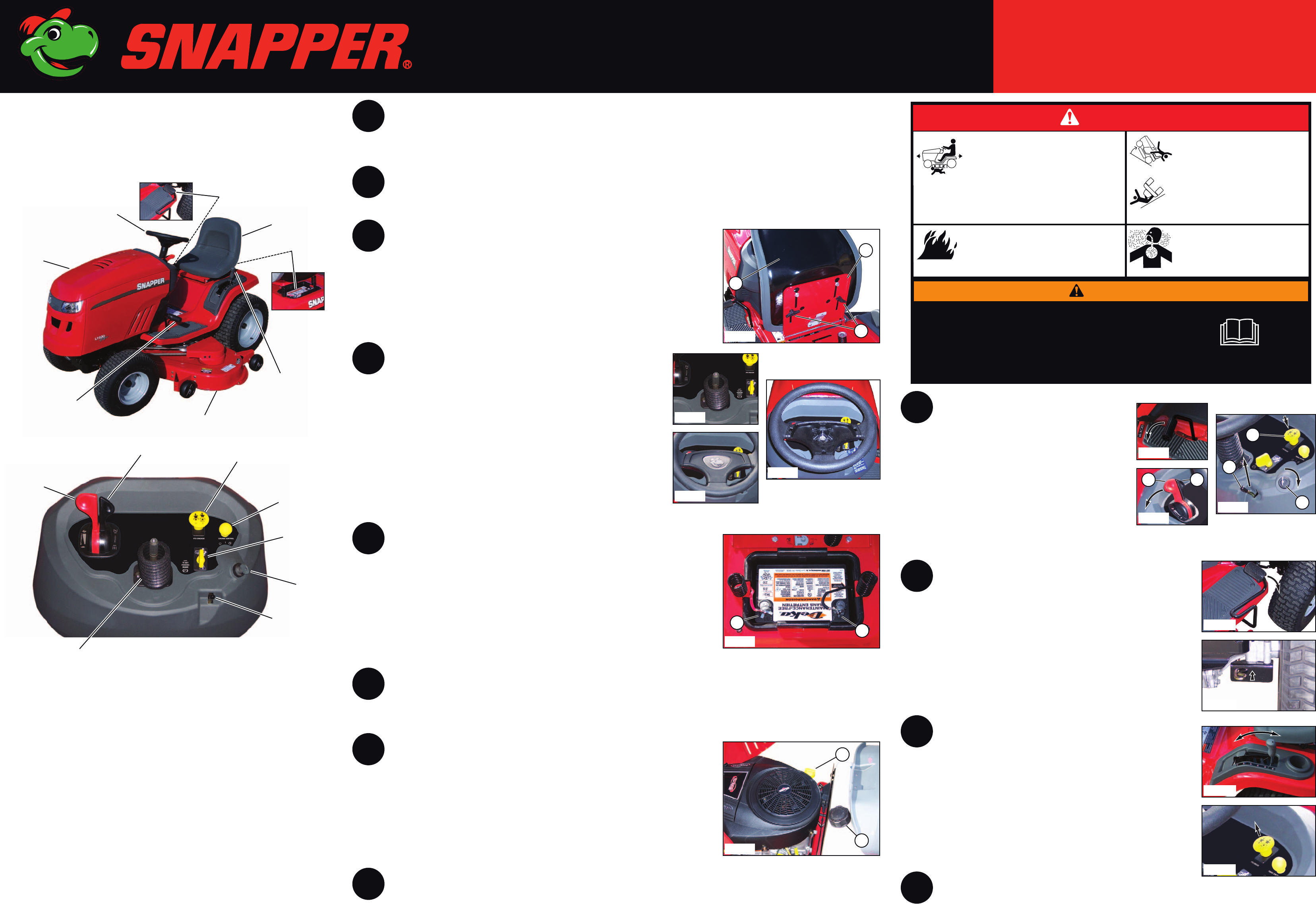
Unit Features and Controls
Throttle
Control
Ignition
Switch
Cruise
Control
PTO (Blade
Engage)
Switch
Choke
Control
Reverse
Mowing Option
(RMO) Switch
Parking Brake
Lever
• Manual Packet
• Seat
• Steering Wheel
• Steering Shaft Bellows
• Steering Wheel Cover
• Hardware Bag including:
• Wing Bolt (2)
• Small Washer (2)
• Hex Bolt (1)
• Large Washer (1)
• Carriage Bolt (2)
• Wing Nut (2)
• Terminal Cover
• Set of two Ignition Keys
• Utility Knife
•Pry Bar
• Tin Snips or Banding Cutter
• Unleaded Fuel (Minimum of 87 Octane)
• 6-10 Amp Battery Charger
• Tire Pressure Gauge
• 3/8” Socket Wrench
7
6
5
4
3
2
1
10
Avoid serious injury or death:
• Know the location and function of
all controls.
• Keep safety devices (guards, shields,
switches, etc.) in place and working.
• Remove objects that could be thrown by the blade.
• Be sure blade(s) and engine are stopped before
placing hands or feet near blade(s).
• When leaving machine, shut off, remove key, and
set parking brake.
WARNING
•Read the operator's manual
before usingthisproduct.
Roll-over hazard
Operating on slopes can cause loss of
control and roll-overs.
• If you cannot back-up a hill, do not drive
on it.
• If machine stops while going uphill,
stop the blades and back down slowly.
• Avoid sudden turns.
• Go up and down slopes, not across.
DANGER
Amputation hazard
Rotating blades cut off arms and legs.
• Stop the mower when children or others are
near.
• Do not carry riders (especially children) even
with the blades off. They may fall off or return
for another ride when you are not expecting it.
• Look down and behind before and while
backing.
Carbon monoxide hazard
The engine emits poisonous carbon
monoxide gas.
• Avoid inhaling exhaust fumes.
• Only operate outdoors.
Fire hazard
Gasoline is flammable. Yard debris is combustible.
• Allow engine to cool for at least 3 minutes
before refueling.
• Keep unit cleaned of debris.
10º Max.
10º Max.
11
12
9
LT24520 - SLT24520 - CLT24520
Steering Wheel
(Removed for Clarity)
8
Figure 4
Figure 2
Figure 3
Figure 1
Figure 5
Figure 6
Figure 7
Figure 9
Figure 8
Figure 10
Figure 11
Figure 12
Figure 13
A
B
B
A
C
A
B
C
A
B
A
B
Items Needed for Assembly
Items Included with Unit
© Briggs & Stratton Corporation
We reserve the right to improve our products and make changes in specifications, designs, and standard equipment without notice and without incurring obligation.
Form No. 7102102 (I.R. 12/17/2007)
TP 1099-5317-IR-TC-N
Steering Wheel
Mower
Deck
Deck Lift
Lever
Seat
Brake
Pedal
Tractor
Hood
Speed Control
Pedal
Battery