1
Installation
1. Park the machine on a flat, level surface. Turn off the PTO,
engage the parking brake, turn off the ignition, remove the
ignition key, and disconnect the spark plug wire(s).
2. Raise the seat plate to gain access to the motion control
arms and dampener controls.
3. Loosen and remove the 5/16-18 hex nylock nuts (A, Figure
1) that secure the dampener controls (B) to the motion
control arms (C). Discard the 5/16-18 hex nylock nuts.
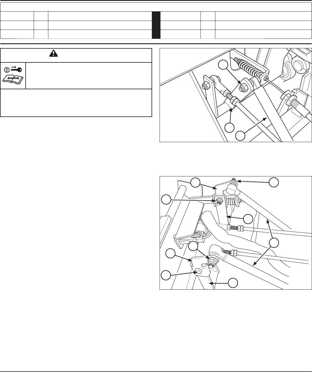
4. See Figure 2. Mount the left motion control tab (A, Figure
2) onto the left side of the left motion control arm (B) so
that the tab is pointing towards the rear of the machine and
secure using a 5/16-18 X 1” bolt (C) and 5/16-18 nylock
flange nut (D).
5. See Figure 2. Mount the right motion control tab (E) onto
the right side of the right motion control arm (F) so that the
tab is pointing towards the rear of the machine and secure
using a 5/16-18 X 1” bolt and 5/16-18 nylock flange nut.
6. Install the dampener controls (G) to the motion control tabs
and secure using 5/16-18 nylock flange nuts as shown in
figure 2.
Installation
Instructions
Motion Control Retro Fit Kit
Part No. 5600266
For Ferris IS1500Z and Simplicity Citation Series Zero-Turn Riding Mowers
S/N: 2012636130 through 2013170251
Kit Contents
Part No. Qty. Description Part No. Qty. Description
5404325A 1 Tab, Motion Control, Retro Fit - RH 5025011X8 2 Bolt, 5/16-18 X 1 GD5 YZ
5404369A 1 Tab, Motion Control, Retro Fit - LH 5025392 4 Nut, 5/16-18 Hex Nylock Flange
WARNING
Remove the ignition key prior to performing
maintenance on the unit.
Before beginning any service work turn off the PTO, engage
the parking brake, turn off the ignition, remove the ignition
key, and disconnect the spark plug wire(s).
Form No.: 5404370
Revision: A
Rev. Date: 03/2009
TP 200-7411-A-SK-F
Copyright © 2009 Briggs & Stratton Power Products Group LLC
Milwaukee, WI, USA. All rights reserved.
C
A
Figure 1. Existing Motion Control Setup
A. 5/16-18 Hex Nylock Nuts
B. Dampener Controls
C. Motion Control Arms
Figure 2. New Dampener Tabs Installed
A. Left Motion Control Tab
B. Left Motion Control Arm
C. 5/16-18 X 1” Bolt
D. 5/16-18 Nylock Flange Nut
E. Right Motion Control Tab
F. Right Motion Control Arm
G. Dampener Control
B
D
E
A
D
C
G
F
B
D


