


6 — English
ASSEMBLY
UNPACKING
This product requires assembly.
Carefully remove the product and any accessories from
the box. Make sure that all items listed in the packing list
are included.
Inspect the product carefully to make sure no breakage
or damage occurred during shipping.
Do not discard the packing material until you have care-
fully inspected and satisfactorily operated the product.
If any parts are damaged or missing, please call
1-800-860-4050 for assistance.
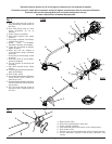
PACKING LIST
C430
Trimmer Assembly
Pro Cut II String Head
Spool Retainer
Front Handle
Curved Shaft Grass Deflector
Bottle of 4-Cycle Lubricant
Oil Fill Funnel
Hanger Cap
Operator’s Manual
S430
Trimmer Assembly
Pro Cut II String Head
Spool Retainer
Front Handle
Straight Shaft Grass Deflector
Bottle of 4-Cycle Lubricant
Oil Fill Funnel
Hanger Cap
Operator’s Manual
WARNING:
If any parts are damaged or missing do not operate this
product until the parts are replaced. Failure to heed this
warning could result in serious personal injury.
WARNING:
Do not attempt to modify this product or create acces-
sories not recommended for use with this product. Any
such alteration or modification is misuse and could result
in a hazardous condition leading to possible serious
personal injury.
WARNING:
To prevent accidental starting that could cause serious
personal injury, always disconnect the engine spark plug
wire from the spark plug when assembling parts.
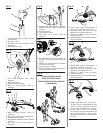
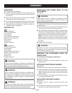
INSTALLING THE POWER HEAD TO THE
ATTACHMENT
See Figure 2.
WARNING:
Never install, remove, or adjust any attachment while
power head is running. Failure to stop the engine can
cause serious personal injury.
The attachment connects to the power head by means of
a coupler device.
Loosen the knob on the coupler of the power head shaft
and remove the end cap from the attachment.
Push in the button located on the attachment shaft. Align
the button with the guide recess on the power head coupler
and slide the two shafts together. Rotate the attachment
shaft until the button locks into the positioning hole.
NOTE: If the button does not release completely in the
positioning hole, the shafts are not locked into place.
Slightly rotate from side to side until the button is locked
into place.
Tighten the knob securely.
WARNING:
Be certain the knob is fully tightened before operating
equipment; check it periodically for tightness during use
to avoid serious personal injury.
REMOVING THE ATTACHMENT FROM THE
POWER HEAD
For removing or changing the attachment:
Loosen the knob.
Push in the button and twist the shafts to remove and
separate ends.
ATTACHING THE STORAGE HANGER
See Figure 3.
There are two ways to hang your attachment for storage.
To use the hanger cap, push in the button and place the
hanger cap over end of the lower end attachment shaft.
Slightly rotate the cap from side to side until the button
locks into place.
The secondary hole in the attachment shaft can be used
for hanging purposes as well.
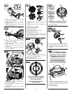
ATTACHING THE FRONT HANDLE
See Figure 4.
Remove wing nut, washer, and bolt from the front
handle.
Install the front handle onto the top side of the drive shaft
housing in the area indicated by the label.