


7 — English
ASSEMBLY
WARNING:
If any parts are damaged or missing do not operate this
product until the parts are replaced. Use of this product
with damaged or missing parts could result in serious
personal injury.
WARNING:
Do not attempt to modify this product or create acces-
sories not recommended for use with this product. Any
such alteration or modification is misuse and could result
in a hazardous condition leading to possible serious
personal injury.
WARNING:
To prevent accidental starting that could cause serious
personal injury, always disconnect the engine spark plug
wire from the spark plug when assembling parts.
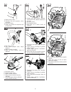
INSTALLING THE POWER HEAD TO THE
ATTACHMENT
See Figure 3.
WARNING:
Never install, remove, or adjust any attachment while
power head is running. Failure to stop the engine can
cause serious personal injury.
The attachment connects to the power head by means of
a coupler device.
Loosen the knob on the coupler of the power head shaft
and remove the hanger cap from the attachment.
Push in the button located on the trimmer attachment.
Align the button with the guide recess on the power
head coupler and slide the two shafts together. Rotate
the trimmer attachment until the button locks into the
positioning hole.
NOTE: If the button does not release completely in the
positioning hole, the shafts are not locked into place.
Slightly rotate from side to side until the button is locked
into place.
Tighten the knob securely.
WARNING:
Be certain the knob is fully tightened before operating
equipment; check it periodically for tightness during use
to avoid serious personal injury.
REMOVING THE ATTACHMENT FROM THE
POWER HEAD
For removing or changing the attachment:
Loosen the knob.
Push in the button and twist the shafts to remove and
separate ends.
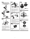
ATTACHING THE STORAGE HANGER
See Figure 4.
There are two ways to hang your attachment for storage:
To use the hanger cap, push in the button and place
the hanger cap over end of trimmer attachment. Slightly
rotate the cap from side to side until the button locks into
place.
The secondary hole in the trimmer attachment can be
used for hanging purposes as well.
ATTACHING THE FRONT HANDLE
See Figure 5.
Remove wing nut, washer, and bolt from the front
handle.
Install the front handle onto the top side of the drive shaft
housing in the area indicated by the label.
NOTE: The open side of the handle should face the
operator.
Place the bolt through the front handle.
NOTE: The hex bolt head fits inside the hex recess molded
into one side of the handle.
Reinstall the washer and wing nut.
Tighten wing nut securely.
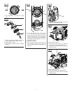
ATTACHING THE GRASS DEFLECTOR
WARNING:
The line cutting blade on the grass deflector is sharp.
Avoid contact with the blade. Failure to avoid contact
can result in serious personal injury.
TO ATTACH THE CURVED SHAFT GRASS
DEFLECTOR - CS26
See Figure 6.
Remove hex screw, washer, and wing nut from grass
deflector.
Press the grass deflector onto the bottom of the curved
shaft as shown.
Insert the hex screw through the grass deflector and the
bracket on the curved shaft.
Place the washer on the hex screw.
Place the wing nut on the hex screw and tighten
securely.