


USERS INFORMATION MANUAL
FOR GAS FIRED BOILERS
WARNING: If the information in this manual is not followed exactly, a fire or explosion may result
causing property damage, personal injury or loss of life.
- Do not store or use gasoline or other flammable vapors and liquids or other combustible
materials in the vicinity of this or any other appliance. To do so may result in an explosion or
fire.
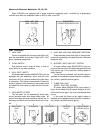
- WHAT TO DO IF YOU SMELL GAS
• Do not try to light any appliance.
• Do not touch any electrical switch; do not use any phone in your building.
• Immediately call your gas supplier from a neighbor's phone. Follow the gas supplier's
instructions.
• If you cannot reach your gas supplier, call the fire department.
- Installation and service must be performed by a qualified installer, service agency or the gas
supplier.
CAUTIONS: Propane gas is heavier than air and sinks to the ground. Exercise extreme care in lighting heater
in confined areas.
Do not use this boiler if any part has been under water. Immediately call a qualified service technician to
inspect the boiler and to replace any part of the control system and any gas control which has been under water.
Should overheating occur or the gas supply fail to shut off, do not turn off or disconnect the electrical supply
to the pump. Instead, shut off the gas supply at a location external to the appliance.
Raypak recommends that this manual be reviewed thoroughly before installing your Raypak Boiler. If there
are any questions which this manual does not answer please contact your local Raypak representative or the
factory.
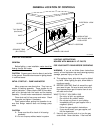
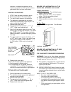
OPERATING CONTROLS
Model W1 with On/Off Controls
The boiler is equipped with an adjustable tankstat. Set dial for desired temperature.
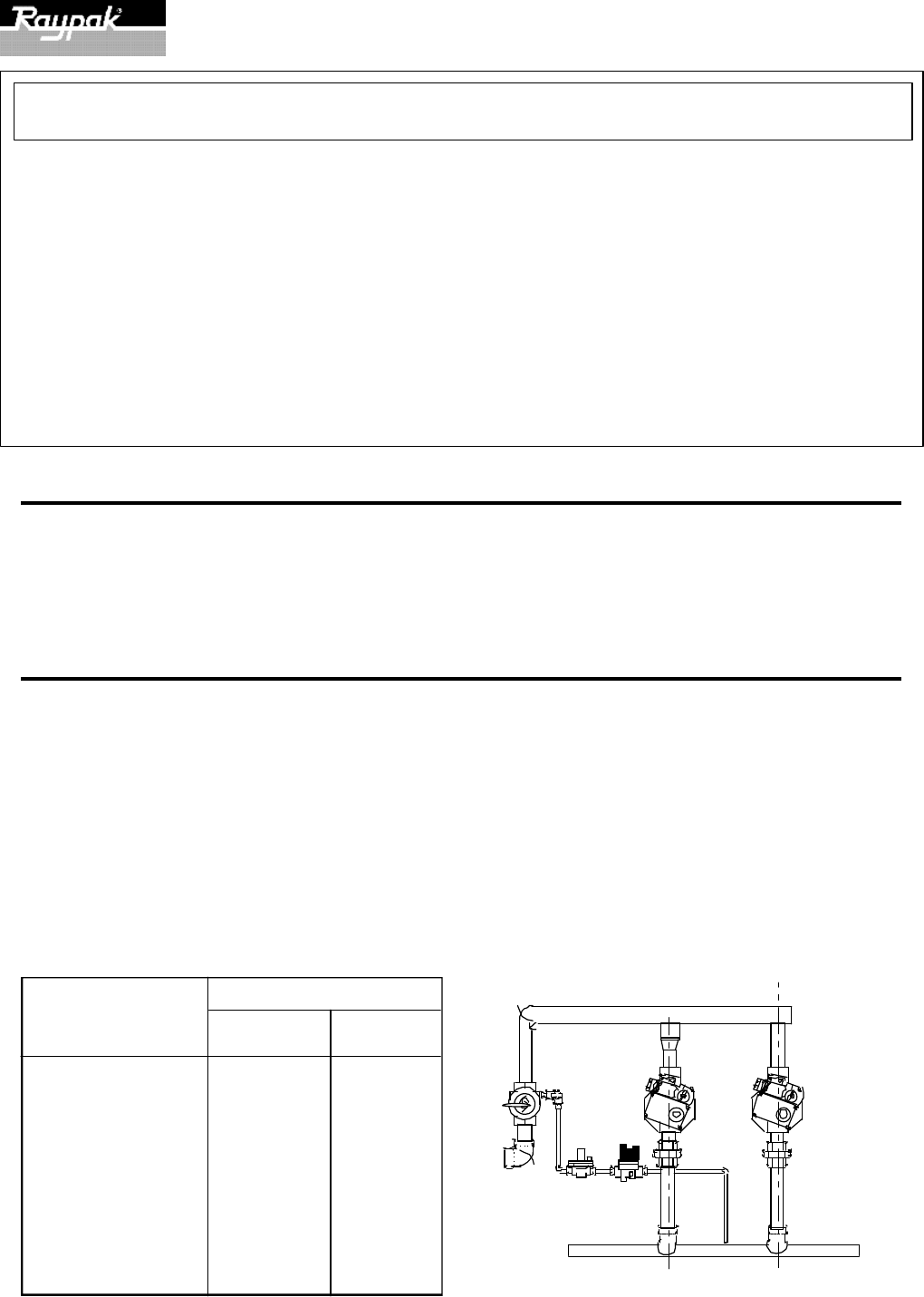
Models with Mechanical Modulation: H1, H5, W2, N, R
Sizes 133 through 1826. These boilers are equipped with modulating gas valves. They have one or more valves
in addition to the main electric gas valve. Their purpose is to adjust the firing rate to meet the required load. The
modulator will throttle the boiler input to meet the system demand. The valve has a remote capillary bulb immersed
in a well at the header outlet to maintain a constant outlet water temperature. When multiple valves are furnished,
they can be staged to give greater flexibility of control. Consult the dial setting tag attached to the control for your
desired water temperature.
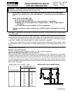
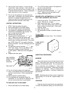
MODULATING VALVE CHART —7000
TEMPERATURE —°F
N H
DIAL POSITION W R
Lo 110 150
1 117 157
2 124 164
3 130 170
4 137 177
5 143 183
6 150 190
7 156 196
8 163 203
Hi 170 210
Fig. # 8936.1
CATALOG NO.: 2000.52G
Effective: 06-01-00
Replaces: 07-01-94
P/N 240412
MODULATING VALVE (ROBERTSHAW)