


DC CIRCUIT BREAKER
The maximum current available from the battery charger
circuit is 15 amps. An automatic DC circuit breaker has been
provided to protect the circuit from overloads and assure that
the battery gets recharged. If an overload occurs, the circuit
breaker will trip. After it cools, it will automatically reset itself.
The battery’s maximum rate of charge will eventually reduce to
less than 15 amps and then to zero as the battery approaches
a 100 percent state of charge.
LOW OIL SHUTDOWN
Some units are equipped with low oil shutdown. If the oil
level becomes lower than required, the generator set will
automatically shut off. This protects your generator set from
operating without proper lubrication.
If generator shuts off and the oil level is according to
specifications, check to see if generator is sitting at an angle
that forces oil to shift. Place on an even surface to correct this.
If engine fails to start, the oil level may not be sufficient to
deactivate low oil level switch. Be sure the sump is completely
full of oil.
Note: On Models PM0477023 & PC0477023 you will
have to crank the engine 1-2 seconds to build up enough
pressure to open the shutdown switch.
INFREQUENT SERVICE
If the unit is used infrequently, difficult starting may result.
To eliminate hard starting, run the generator at least 30 minutes
every month. Also, if the unit will not be used for some time, it
is a good idea to drain the fuel from the carburetor and gas
tank.
LONG TERM STORAGE
When the generator set is not being operated or is being
stored more than one month, follow these instructions:
1.Replenish engine oil to upper level.
2.Drain gasoline from fuel tank, fuel line and carburetor.
3.Pour about one teaspoon of engine oil through the spark
plug hole, pull the recoil starter several times and replace
the plug. Then pull the starter until you feel the piston is on
its compression stroke and leave it in that position. This
closes both the intake and exhaust valves to prevent the
inside of the cylinder from rusting.
4.Cover the unit and store in a clean, dry place that is well
ventilated away from open flame or sparks.
NOTE: The use of a fuel additive, such as STA-BIL
®
, or
an equivalent, will minimize the formulation of fuel gum
deposits during storage. Such an additive may be added
to the gasoline in the fuel tank of the engine, or to the
gasoline in a storage container.
WARNING: To avoid possible personal injury
or equipment damage, a registered electrician or
an authorized service representative should
perform installation and all service. Under no
circumstances should an unqualified person
attempt to wire into an utility circuit.
To avoid backfeeding into utility systems, isolation of the
residence electrical system is required.
Before temporary connection of the generator to the
residence electrical system, turn off the main switch.
If your generator is to be used as a stand-by power source
in case of utility power failure, it should be installed by a
registered electrician and in compliance with all applicable local
electrical codes.
Proper use requires that a double throw transfer switch be
installed by a licensed qualified electrician so that the building's
electrical circuits may be safely switched between utility power
and the generator's output, thereby preventing backfeed into
the power utility's electrical system.
WARNING: To avoid backfeeding into utility
systems, isolation of the residence electrical
system is required. Before temporary connection
of a generator to the residence electrical system
turn off the main switch. Before making permanent
connections a double throw transfer switch must
be installed. To avoid electrocution or property
damage, only a trained electrician should connect
generator to residence electrical system.
California law requires isolation of the residence
electrical system before connecting a generator to
residence electrical systems.
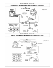
If your generator is equipped with electric start, refer
to one of the wiring diagrams on the following page.
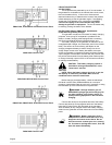
FIGURE A
An “Off-On-Start” rotary key switch is provided on the recoil
end panel on some models. All necessary wiring is provided.
The battery is customer provided. #8 AWG (American Wire
Gauge) copper wire lead with ring terminals make battery
hookup quite simple. Connect the lead hooked to the chassis to
the negative (-) battery terminal and the lead from the starter
solenoid to the positive (+) battery terminal with the appropriate
bolts, lock washers and nuts. The orange wire connected to the
solenoid and positive (+) battery terminal provides battery
charging up to 16 amps.
Your engine may be equipped with a trickle charge system.
The 14 AWG (American Wire Gauge) red wire which comes
from the engine should be connected to the positive battery
terminal (see engine operator manual).
FIGURE B
An “Off-On-Start” rotary key switch is provided on the
control panel on other models. All necessary wiring is provided.
The battery is customer provided. #8 AWG (American Wire
Gauge) copper wire lead with ring terminals make battery
hookup quite simple. Connect the lead hooked to the chassis to
the negative (-) battery terminal and the lead from the starter
solenoid to the positive (+) battery terminal with the appropriate
bolts, lock washers and nuts.
WARNING: Batteries contain sulfuric acid
(when filled). May contain explosive gasses.
Always abide by safety warnings provided
with the battery.
-Keep sparks, flame and cigarettes away.
-Hydrogen gas is generated during
charging and discharging.
-Always shield eyes, protect skin and
clothing when working near batteries.
8
English
INSTALLATION
ELECTRIC START WIRING