


6
ASSEMBLY
WARNING: If received assembled,
repeatall steps toensure your unitis properly
assembled and all fasteners are secure.
Examine parts fordamage. Do not use dam-
aged parts.
NOTE: If y ou need assistance or find parts
missing or damaged, call 1-800-554-6723.
TOOLS REQUIRED
S Hex wrench (provided)
INSTALL ING PR UNER ATTACH-
MENT
CAUTION:
When removing or installing at-
tachments, place the uniton a f lat surface for
stability.
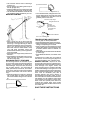
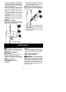
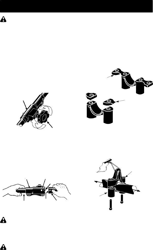
1. Loosen the coupler by turning the knob
counterclockwise.
Coupler
Knob
LOOSEN
TIGHTEN
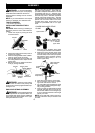
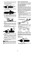
2. Remove theshaft cap from the pruner at-
tachment (if present).
3. Position locking/release button of attach-
ment into guide recess of coupler.
4. Push theattachment intothe coupleruntil
the locking/release button snaps into the
primary hole.
5. Before using theunit, tightenthe knobse-
curely by turning clockwise.
Coupler Primary Hole
Upper
Shaft
Locking/
Release
Button
Lower
Attachment
Guide Recess
WARNING: Make sure t he locking/
release button is locked in the primary hole
and theknob is securely tightened before op-
erating the unit.
SHOULDER STRAP A SSEMBLY
WARNING: Propershoulder strapand
handle adjustments are required before use.
The shoulder strap clamp m ust be installed a s
shown above the assist handle on the upper
shaft (powerhead end of uni t).
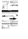
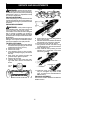
NOTE: The lower shoulder strap clamp has
two spacer tabs attached. These tabs are
providedtoadapt this attachmentfor usewith
powerheads that have a 1″ diameter upper
shaft (theshoulderstrapclampwillnottighten
downsecurely onthe1″diameter uppershaft
without using these spacer tabs). The tabs
must bebrokenoffcompletely be foreuseand
placed over the screw holes on the lower
shoulder strap clamp. These tabs are not
needed for powerheads with a 7/8″ upper
shaft.
Spacer Tabs
LOWER SHOUL DER STRAP
CLAMP
Spacer Tabs
positioned for use
on 1″ diameter
upper shaft
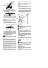
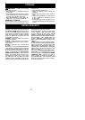
1. Place the upper shoulder strap clamp
over theupper shaftabovethehandlebar.
2. Position the l ower shoulder strap clamp
under the upper shaft and align theupper
andlowerclampscrewholes (usespacer
tabs between upper and lower clamps if
necessary to secure clamp, i.e. for 1″ di-
ameter upper shaft).
Upper Shoulder
Strap Clamp
Screws
Lower Shoulder
Strap Clamp
POWERHEAD
END
ATTACHMENT
END
3. Insert two screws into the screw holes.
4. Secure shoulder strap clamp by tighten-
ing screws with the hex w rench.
5. Try o n shoulder strap and adjust f or fit and
balance before startin g theengine orbegin-
ning a cutting operation.
6. Insertyourrightarmandhead throughthe
shoulder strap and allowit to rest on your
left shoulder . Make sure the danger sign
is onyourback andthe hookis tothe right
side of your waist.
NOTE: A one-half twist is built in the shoul-
der strap to allow the s trap to r est flat on the
shoulder.