


11
For assembly of optional attachments (see
list on page13), refer to the ASSEMBLYsec-
tion of the applicable attachment instruction
manual.
SHOULDER STRAP ASSEMBLY
WARNING: Proper shoulder strap
adjustments must be made with the engine
completely stopped before using unit.
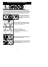
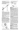
1. Try on shoulder strap and adjust for fit
and balance beforestarting theengine or
beginning a cutting operation.
2. Insert your right arm and head through
the shoulder strap and allow it to rest on
your left shoulder. Make sure the danger
sign is centered on your back and the
hook is to the right side of your waist.
NOTE: A one-half twist is built in the shoul-
der strap to allow the strap to rest flat on the
shoulder.
3. Adjust the strap, allowing the hook to be
about 3 -- 6 inches (8 -- 15 cm) below the
wai st.
4. Fasten the strap hook to the clamp lo-
cated betweenthethrottlehandle a ndthe
assist handle and lift the tool to the oper-
ating position.
NOTE: It may be necessary to relocate the
shoulder strap clamp on the shaft for proper
balancing of unit.
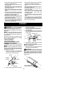
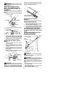
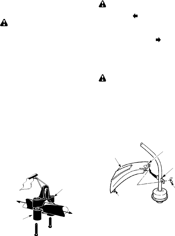
TO RELOCATE SHOULDER STRAP
CLAMP:
1. Loosen and remove both clamp screws.
2. Place the upper shoulder strap clamp
over the upper shaft.
3. Position the lower shoulder strap clamp
under theupper shaft andalign theupper
and lower clamp screw holes.
Upper Shoulder
Strap Clamp
Screws
Lower Shoulder
Strap Clamp
POWERHEAD
END
ATTACHMENT
END
4. Insert two screws into the screw holes.
5. Secure shoulder strap clamp by tighten-
ing screws with a hex wrench.
ADJUSTING THE ASSIST HANDLE
WARNING: When adjusting the as-
sist handle, be sure it remains between the
coupler and the
lower arrow (closest to
coupler) on the safety label to ensure proper
balancing of unit. W hen adjusting the assist
handle orhandlebar during useof optionalat-
tachments, it must be repositioned between
the throttle trigger and the
upper arrow
(closest to engine) on the safety label.
1. Loo sen wing nut on handle.
2. Rotate the handle on the shaft to an up-
right position; retighten wing nut.
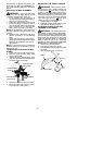
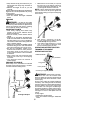
ATTACHING SHIELD (FOR LINE
TRIMMER ATTACHMENT)
WARNING: The shield must be prop-
erly installed.The shiel dprovides partialprotec-
tion from the risk of thrown objects to the opera-
tor and others and is equipped with a line limiter
blade which cuts excess line to the proper
length. The line limiter blade (on underside of
shield) is sharp and can cut you. For proper
orientatio n of shield, see KNOW YOUR TRIM-
MER illustration in OPERATION section.
1. Remove wing nut from shield.
2. Insert bracket into slot as shown.
3. Pivotshielduntilboltpasses throughhole
in bracket.
4. Securely tighten wing nut onto bolt.
Slot
Shield
Wing
Nut
Bracket
Line Limiter Blade