


8
S Be attentive when using the snowthrower,
and stay alert for holes in the terrain a nd
other hidden hazards.
S Make sure the rotor will spin freely before
attaching the snowthrower to the power-
head.
S Ifthe rotorwillnot rotatefreely duetofrozen
ice, thaw the unit before thoroughly before
attempting to operate under power.
S Keep the rotor clear of debris.
S Do not throw snow near other people. The
snow thrower could propel small objects at
high speed causing injury .
S After striking a foreign object, stop the e n -
gine,disconnectspark plugandinspect the
snowthrower for damage and repair if nec-
essary before restarting unit.
S Never operate the snowthrower nearglass
enclosures, automobiles and trucks.
S Never attempt to use thesnowthrower ona
roof.
S Never operate the snowthrower n e ar win-
dow wells, dropoffs, etc.
S Never discharge snow ontopublic roads or
near moving traffic.
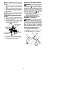
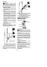
S Clear snow from slopes by going up and
down; never across. Use caution when
changing directions. Never clear snow
from steep slopes.
S Letsnowthrowerrunfor afew minutes after
clearing snow so moving parts do not
freeze.
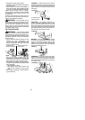
S Look behind and use care when backing
up. Exercisecautionto avoidslippingorfal-
ling, especially when operating in reverse.
S Know how to stop quickly.
ASSEMBLY
WARNING: If received assembled,
repeatall steps toensure your unitis properly
assembled and all fasteners are secure.
Examine parts for dam age. Do not use dam-
aged parts.
NOTE: If you need assistance or find parts
missing or damaged, call 1-800-554-6723.
It is normal for the fuel filter to rattle in the
empty fuel tank.
Finding fuelor oil residue onmuffler isnormal
due to carburetor adjustments and testing
done by the manufacturer.
TOOLS REQUIRED
S Hex wrench (provided)
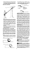
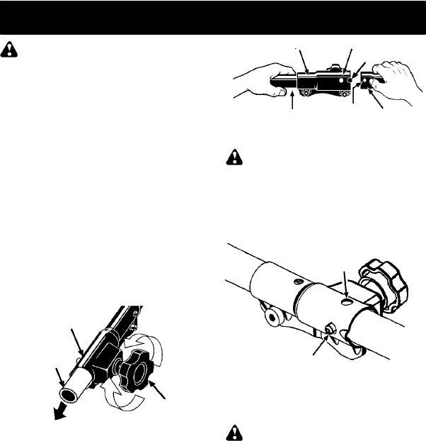
INSTALLING PRUNER OR LINE
TRIMMER ATTACHMENTS
CAUTION:
When removing or installing at-
tachments, place the uniton aflat surface for
stability.
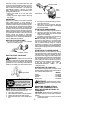
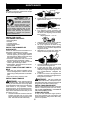
1. Loosen the coupler by turning the knob
counterclockwise.
Coupler
Knob
LOOSEN
TIGHTEN
Shipping
protector
2. Remove shipping protector fromcoupler.
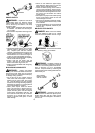
3. Remove the shaft cap from the attach-
ment (if present).
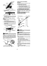
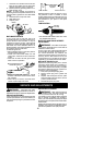
4. Position locking/release button ofattach-
ment into guide recess of coupler .
5. Pushtheattachment intothe coupleruntil
the locking/release button snaps into the
primary hole.
6. Beforeusing theunit,tightentheknobse-
curely by turning clockwise.
Coupler Primary Hole
Upper
Shaft
Locking/
Release
Button
Lower
Attachment
Guide Recess
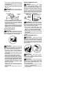
WARNING: Make sure the locking/
release button i s locked in the primary hole
and theknob is securely tightened beforeop-
erating the unit. Al l atta chment s are des igned
to be used in the primary hole unless otherwise
stated in the applicable attachment instruction
manual. Usingthe wrong holecouldlead toseri-
ous injury or dam age to the unit.
Locking/Release
Button in Primary Hole
Secondary Hole
For optional attachments, see the AS-
SEMBL Y section of the applicable attach-
ment instruction manual.
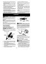
SHOULDER STRAP ASSEMBLY
WARNING: Proper shoulder strap
adjustments m ust be made with the engine
completely stopped before using unit.
1. Try on shoulder strap and adjust for fit
and b alance beforestarting theengine or
beginning a cutting operation .
2. Insert your right arm and head through
the shoulder strap and allow it to rest on
your left shoulder. Make sure the danger
sign is centered on your back and the
hook is to the right side of your waist.