


5
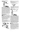
ASSEMBLY INFORMATION --
TRIMMER HEAD
TRIMMER
HEAD
NOTE:
Remove the blade and metal shield
before attaching the plastic shield and trim-
mer head. To remove blade, push in locking
lever and hold. Rotate blade nut until t helock-
ing lever falls into one of the grooves in the
dust cup. Continue to hold the locking lever.
This will keep the shaft from turning while
loosening the blade nut. Remove blade nut
by turning clockwise. Release locking lever.
Remove both washers and blade. To remove
metal shield, loosen and remove the four
mounting screws. See ATTACHING THE
METAL SHIELD and INSTALLATION OF
THE METAL BLADE for illustrations. Be sure
to store all parts and instructions for future
use.
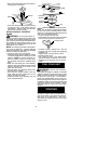
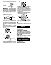
ATTACHING THE PLASTIC SHIELD
AND TRIMMER HEAD
WARNING:
The shield must be prop-
erly installed. The shield provides partial
protection from the risk of thrown objects to
the operator and others and is equipped with
a line limiter blade which cuts excess line to
the proper length. The line limiter blade (on
underside of shield) is sharp and can cut you.
S
Remove wing nut from shield.
S
Insert bracket into slot on shield.
S
Pivot shield unt il bolt passes through hol e in
bracket.
S
Tighten the wing nut securely.
S
If your unit has a plastic cover over the
threads on the threaded shaft, remove the
covering to expose the threads.
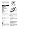
S
Before installing the trimmer head, make
sure the dust cup is positioned on the gear-
box as shown below.
Wing Nut
Dust Cup
Bracket
Slot
Shield
Gearbox
NOTE:
Make sure all parts are proper ly
installed a s shown in the illu s tration b efore
installing the trimmer head.
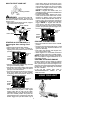
S
Push in locking lever and hold.
S
Rotate dust cup until the locking lever falls
into one of the grooves
.
Locking Lever
S
Continue to hold in locking l ever . Thi s will
keep the shaft from turning while tightening
the trimmer head.
S
Thread trimmer head onto t he shaft in the
direction shown on t he decal. Tighten until
secure.
S
Release locking lever.
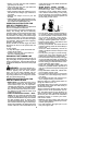
ASSEMBLY INFORMATION -- WEED
BLADE
WEED
BLADE
NOTE:
Remove t he t r immer head and plastic
shield before attaching the metal shield and
installing the weed blade. To remove the trim-
mer head, push in locking lever and hold. Ro-
tate trimmer head until the l ocking lever falls into
one of the grooves i n the dust cup. Continue to
hold in locking lever. This will keep the s haft
from turning while loosening the trimmer head.
Remove trimmer head by turning clockwise.
Release locking lever. To r emove the plastic
shield, loosen and rem ove wing nut. Pivot
shield to releas e brac k e t fro m slot. See AT-
TACHING THE P L ASTICSHIELD ANDTRIM-
ER HEAD for illustration s . Be sure to sto re all
parts and instructions for future use. Never use
the trimm er head with the m etal bl ade installed.
ATTACHING THE METAL SHIELD
DANGER:
The metal shield must be
properly installed on the tool anytime the tool
is used with the blade. The forward tip of the
metal shield helps to reduce the occurrence
of blade thrust which can cause serious injury
such as amputation to the operator or by-
standers. Failure to install the shield in the
position shown can result in serious injury to
the operator. The length of the shield must be
aligned with the length of the tube. The blade
is sharp and can cut you. Be sure to wear
gloves while working with blades.
S
If your unit has a plastic cover over the
threads on the shaft, remove the covering
to expose the threads.