


A PRODUCT OF THE GENFLEX SYSTEM
MADE IN THE USA
LINK ELECTRONICS, INC.
ANALOG SYNC GENERATOR
812-OP/G
For Future Generations
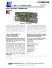
The SPG-812 analog test set (812AT or OP/G) is an
important element of the GenFlex family of products.
The SPG-812 analog test set module allows the user
to select from sixteen (16) different video test
patterns by a front panel switch or through a remote
control unit, the SPG-812TRC. These patterns are
produced in any one of four (4) possible formats:
1. Composite video plus a Y/C pair.
2. SMPTE Component video: Y-Pr-Pb.
3. Red, Green, and Blue. (RGB).
4. Green + Sync, Blue, and Red.
All patterns are produced at 10-bit resolution and use
high-performance hybrid post-filters with integral
output amplifiers. Both NTSC and PAL video
standards are supported.
When genlocking to incoming video, the SPG-812
chassis will have either an analog (812AG or OP/C)
or a digital genlock module (812DG or OP/D)
installed in the bottom slot next to the power supply
The Genlock module places the required timing
pulses on the motherboard buss to allow each
subsequent module to lock to a single reference.
The analog test set offers “infinite window” timing of
horizontal and vertical as well as 360° subcarrier
phasing. Timing information is stored in battery-
backup RAM within the unit’s onboard
microcontroller.
The analog test set module may be installed in any
slot within the SPG-812 chassis except for the slot
dedicated to the audio module. If the 812AT is
installed in the “Genlock Module or Master” slot, it
will serve as the master timebase for all other
modules in the chassis, and the overall unit would
have no genlocking capability. The SPG-812
analog test set uses a single 2-bit mechanical
encoder to control all module functions including
system timing and pattern selection. An eight-
character alpha-numeric display provides a menu
of options for each module parameter.
The 812-OP/G is the plug-in module that provides
16 analog test signals. The test signals are:
1)100% color bars
2) 75% color bars
3) SMPTE color bars
4) 5-Step modulated stairstep
5) 5-step un-modulated stairstep
6) modulated ramp
7) un-modulated ramp
8) 2T/12.5T pulse & bar
9) field square wave
10) SDI pathological pattern
11) 50% multiburst
12), 100% line sweep
13) red field
14) shallow ramp
15) gray
16) black.
The PCO-818 automatic pulse change-over modules operate as independent or synchronized operation. Two
PCO-818 change-over chassis may be interlinked to cause all modules to switch should a failure occur in the
master generator.
LINK ELECTRONICS, INC. 2137 Rust Avenue Cape Girardeau, MO 63703-7668
Phone 573 334 4433
FAX 573 334 9255