


1
© Copyright 2005 Printed
Before You Start
These option assembly instructions contain only
information on assembling the attachment to the main
unit. A detailed Operator’s Manual was supplied with the
main unit when it was purchased. For more specific
information on safety concerns refer to the Operator’s
Manual. Also included in the Operator’s Manual is
important information on operation, adjustment,
troubleshooting, and maintenance for this attachment
(some of these sections do not apply to all options).
A separate Parts Manual for replacement parts can be
purchased from your dealer or available free of charge at
www.landpride.com. Have model and serial numbers
handy when placing an order.
Manual Part Numbers:
• MANUAL 05-15 REAR BLADE. . . . . . . . . . . . . 301-143M
• PARTS BOOK REAR BLADES. . . . . . . . . . . . . .301-143P
• MANUAL 15 LANDSCAPE RAKE . . . . . . . . . . 302-185M
• MANUAL 25 & 35 LANDSCAPE RAKE . . . . . . 302-186M
• PARTS BOOK LANDSCAPE RAKE . . . . . . . . . .302-185P
General Information
These option assembly instructions apply to the RBT15
Series Rear Blades, RB15 Series Rear Blades, RB25
Series Rear Blades, LR15 Series Landscape Rakes &
LR25 Series Landscape Rakes listed below:
300-195A RB/LR15 SUPPORT STAND SHIPOUT
300-196A RB/LR25 SUPPORT STAND SHIPOUT
This kit is designed to adapt to the following Land Pride
products:
RBT1560, RBT1572 & RBT1584
RB1560, RB1572 & RB1584
RB2572, RB2584 & RB2596
LR1560, LR1572, LR1584 & LR1596
LR2572, LR2584 & LR2596
Starting on page 2 is a detailed listing of parts included
in this kit. Use this list as a checklist to inventory parts
received.
When you see this symbol, the subsequent
instructions and warnings are serious - follow
without exception. Your life and the lives of
others depend on it!
!
IMPORTANT: Before you begin, read these
instructions and check to be sure all parts and tools
are accounted for. Please retain these installation
instructions for future reference and parts ordering
information.
RB15, RBT15, RB25, LR15 & LR25
Support Stand
3/01/06
Manual No. 301-222M
Assembly Instructions
!
CAUTION!
Securely support the unit before assembly.
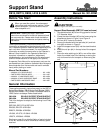
Support Stand Assembly (RBT15 Frameis shown)
1. Use stand bracket (#5) as a drilling guide for the two
1/2" diameter holes.
2. Clamp the stand bracket (#5) to the frame using the
dimensions shown in Figure 1 and Figure 2.
3. Drill two 9/16" holes for the bolts.
4. Secure the bracket with the two bolts (#1) and lock
nuts (#6) as shown in Figure 2.
5. Install the support stand (#3) into the stand bracket
(#5).
6. Install the roll pin (#4) in the top hole of the support
stand.
7. Place the wire retaining pin (#2) in one of the other
holes; the middle hole is for standing or storing the
unit and lower hole for transport or when using the
unit.
Figure 1
Figure 2
18127
18126