


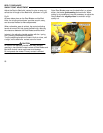
LIFT CHAINS ADJUSTMENT
REELS 4 AND 5 Cont.
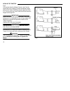
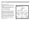
Fig.15. (page 20)
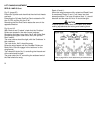
Extend the cylinder and check that the chain bolt heads
are level.
Extending the Cylinder Rod End Clevis rotates the RH
Arm C.C.W. and the LH Arm C.W.
Retracting the Rod End Clevis rotates the arms in the
opposite direction.
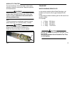
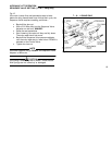
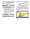
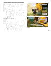
Fig.14 and 16.
With Reels 4 and 5 ‘raised’, check that the ‘Snubber’
Rollers are located in the main frame ‘catchers’.
Shortening the lower inner chain, No.5, will lift the Reel.
Shortening the upper outer chain, No.6, will pull the
Reel ‘inward’.
The outer chains should be tight, with the ‘Snubbers’ in
their catchers.
The inner chain, No.5, should be snug.
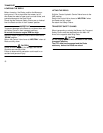
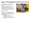
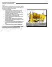
Raise the wing frames until the ‘Snubber’ Rollers on
Reels No’s. 8 and 9 engage in the ‘catchers’ on the
wing frames.
The inboard lift chain No. 9, controlling the inboard end
of the reel should be tight.
The outer chain No.10, controlling the outboard end of
the Reel should be snug.
21
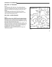
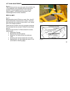
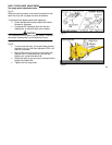
Reels 10 and 11.
When the wing frames are fully raised and Reels 8 and
9 are stowed, Reels 10 and 11 will lower into their
stowed positions. The inner lift chains, No’s.11, should
be slack and the outer lift No’s 12 should be tight.
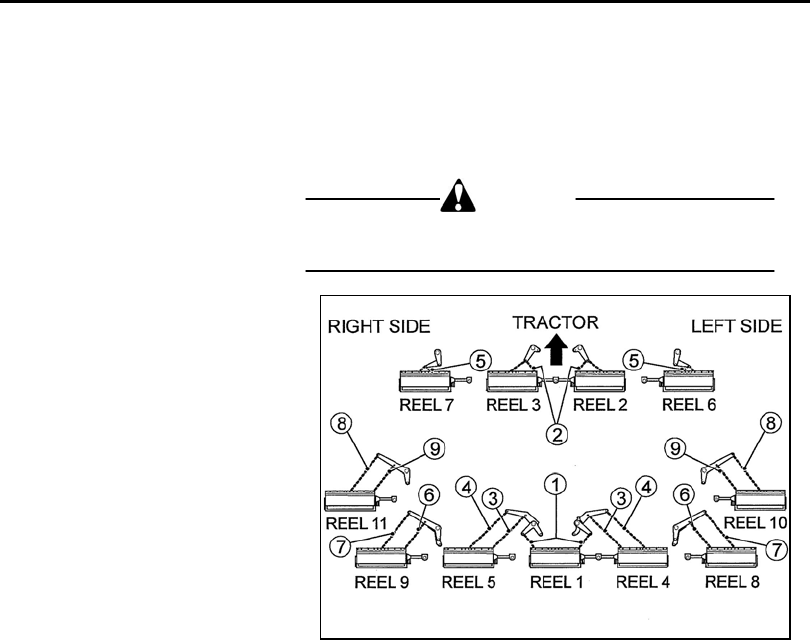
CAUTION
Exercise caution, keep clear of the Reels units when
making adjustments and raising and lowering them.
Refer to page 48 for chain attachment point dimensions.
Fig.16