


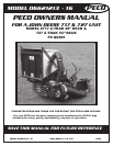
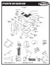

MODEL 06621213 - 16 JOHN DEERE 717 & 727 PECO 7
PECO
ASSEMBLY
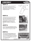
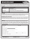
STEP 4:
On the right end of the outer motor mount tube (A)
slide the motor mount arm assembly (B) in. Secure
using (1) detent pin (PN#J0248). Next place the
engine (C) onto the motor mount arm assembly (A).
Secure the engine (C) to the motor mount arm
assembly (B) by using (4) 5/16”-18 x 1-1/2” hex
bolts (PN#K1157) and (4) 5/16”-18 flange nuts
(PN#K1178). Use the picture to the right for more
detail.
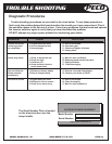
STEP 5:
Secure the boot (A) to the boot plate (B) by using (2)
3/8”-16 x 2” carriage bolts (PN#K1184) and (2) 3/8”-16
flange nuts. Slide and hook the boot & boot plate to the
deck. Use the picture to the right for more detail.
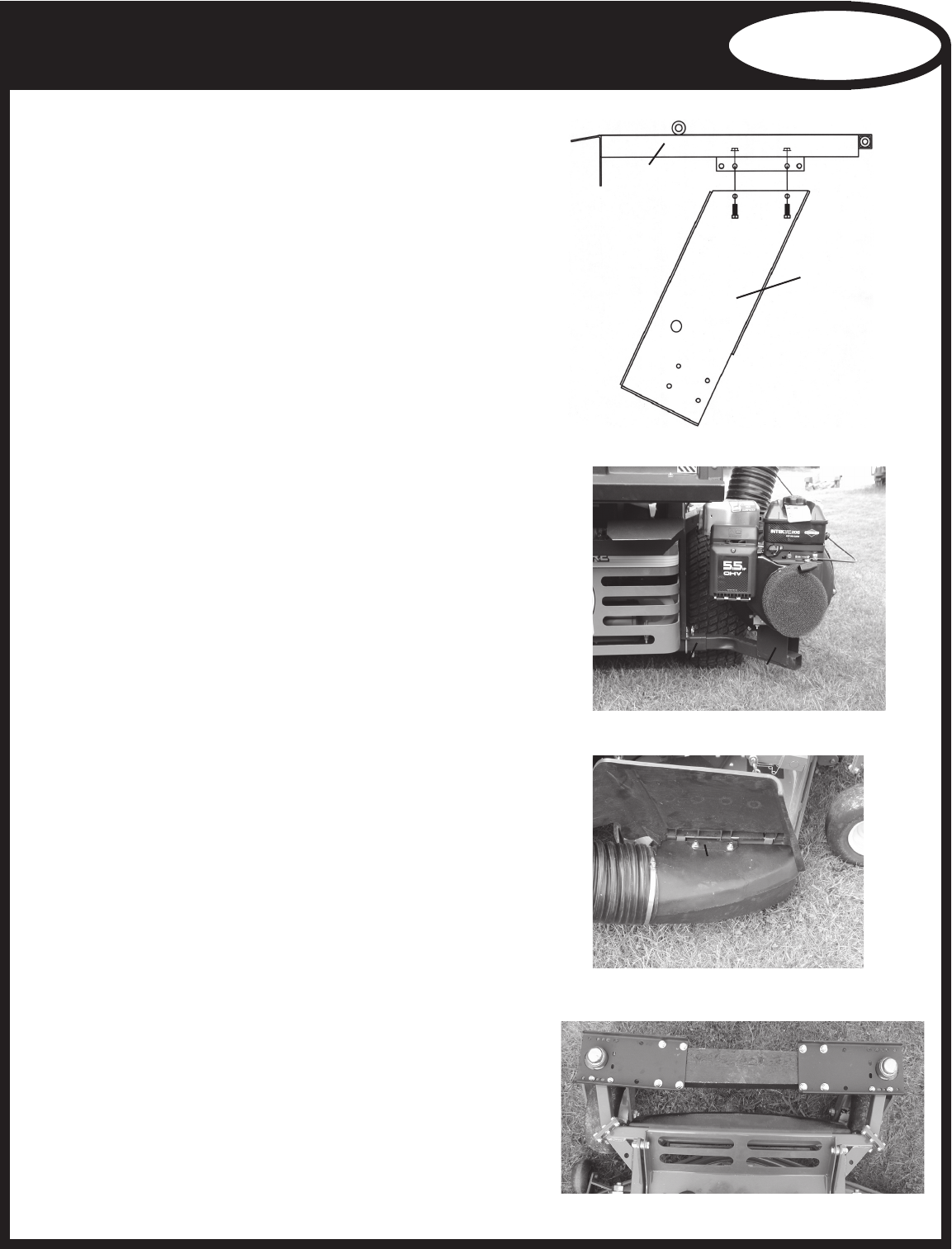
STEP 6:
Mount the left & right weight brackets (A) to the
mower using (2) 3/8”-16 u-bolts (PN#K1432) and
(4) 3/8”-16 flange nuts (PN#K1215). Using a floor
jack secure the weight brackets (A) to the weight (B)
using (4) 1/2”-13 u-bolts (PN#K0331) (2 per side) and
(8) 1/2”-13 flange nuts (PN#K1246). Use the picture
to the right for more detail.
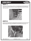
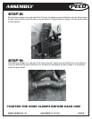
STEP 3:
Place the top frame assembly (A) onto the left and
right main frame side legs (B). Secure the top
frame assembly (A) using (4) 3/8”-16 x 1” hex bolts
(PN#K1191) (2 per side) & (4) 3/8-16 flange
nuts (PN#K1215) (2 per side). Use the diagram to
the right for more detail.
A
B
C
A
B
BOLT LEGS ON
OUTSIDE OF FRAME
A
B
A
A
B